3D Printed Microscope Sub-stage Illuminator
When I found out that my Olympus student monocular compound microscope was designed in the 1950s, the astonishment was immense: based on the quality of images achieved previously with the microscope, I would never have guessed! It has served me extremely well, and as it is my first microscope, I am indebted to it, for it has allowed me to explore whatever microscopic specimens I choose without much trouble.
However, a significant problem with this microscope - and indeed any of a similar design, where a mirror is the primary light source instead of a lamp - is that specimens are not illuminated nearly well enough for crisp, bright images. As a result, there is a very evident lack of contrast and vibrance visible.
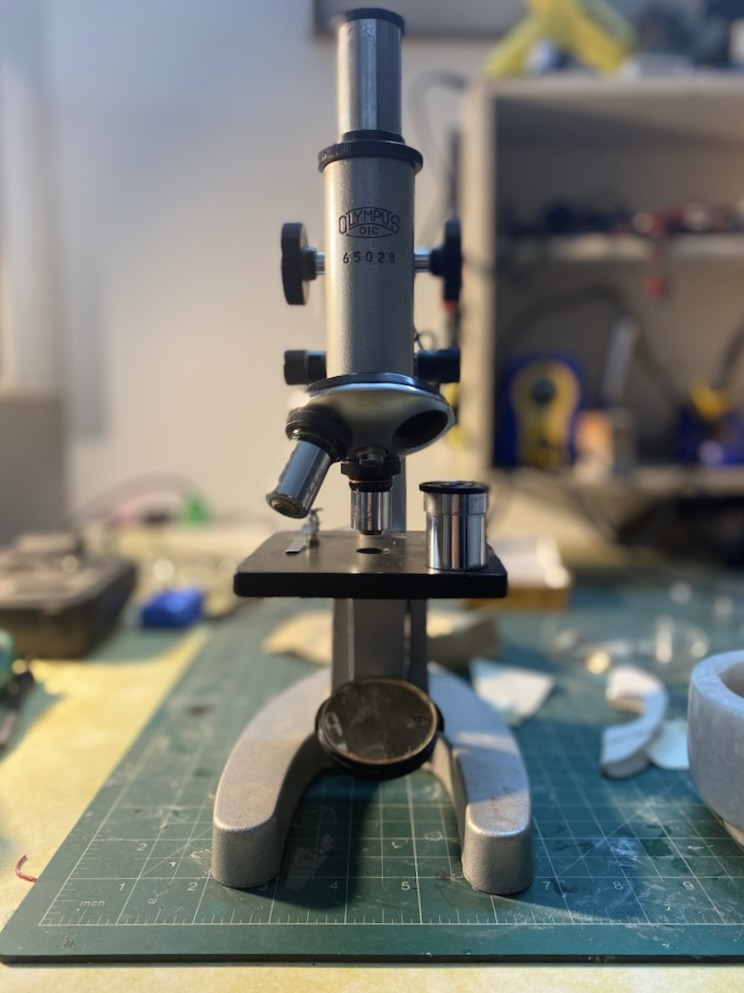
The 3D printer is my Green Lantern’s ring: whatever I imagine, I can create. So naturally, when I decided that I wanted to improve the quality of my images by improving the illumination of my samples, my first thought was let me make an LED lamp which fits exactly into the slot designed for the substage mirror.
Optics
When I was sitting at the drawing table, the idea of going beyond merely an LED bulb attached to the microscope, and instead also adding functionality that could enhance the image further, was irresistible - the limit here was only what would be useful, and what I could dream up.
Due to the age of my microscope, it’s lenses were not in the best shape. Thus, while an increase in magnification was unnecessary, an increase in resolution would be greatly appreciated. Resolution is determined by not just the lenses, but also the wavelength of light being used to image the sample. Light with a smaller wavelength interacts with smaller matter, producing an image of smaller features. Resolution could hence be increased with using light of a higher frequency - such as UV light. I can’t see or image UV light, so I settled on using blue LEDs. The illuminator should then have two “modes”: a white light mode for regular comfortable viewing, and a blue light mode for high-resolution imaging (photographs of which can be converted to greyscale to remove any colour-based artefacts).
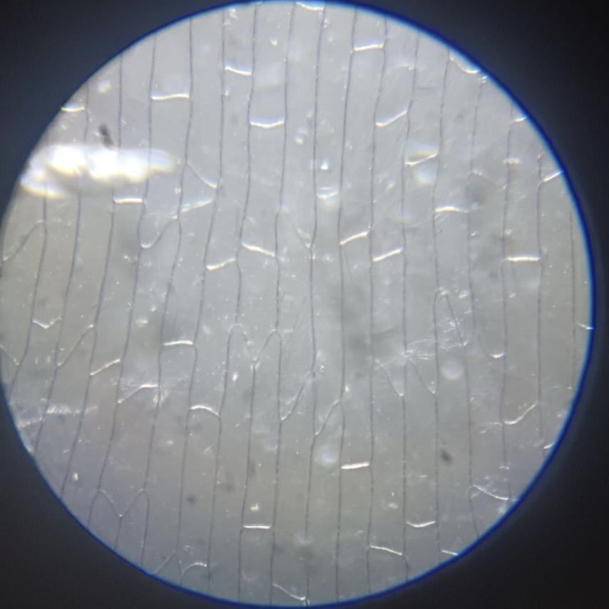
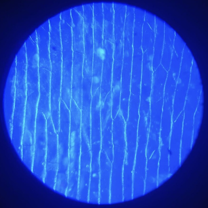
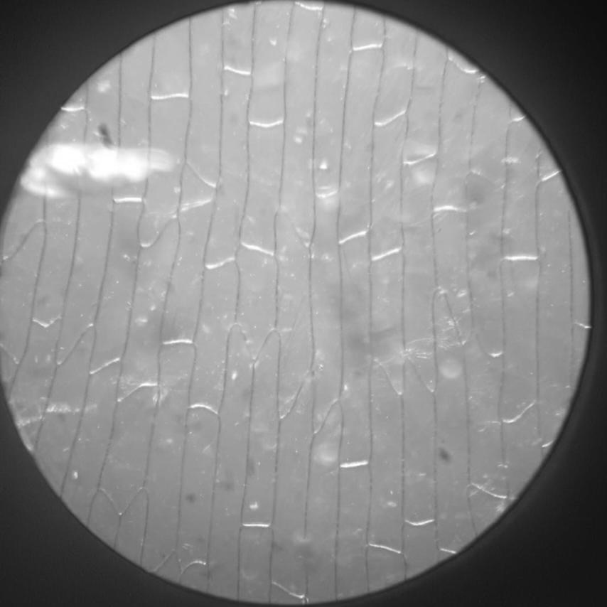
MK-I
Electronics & Circuitry
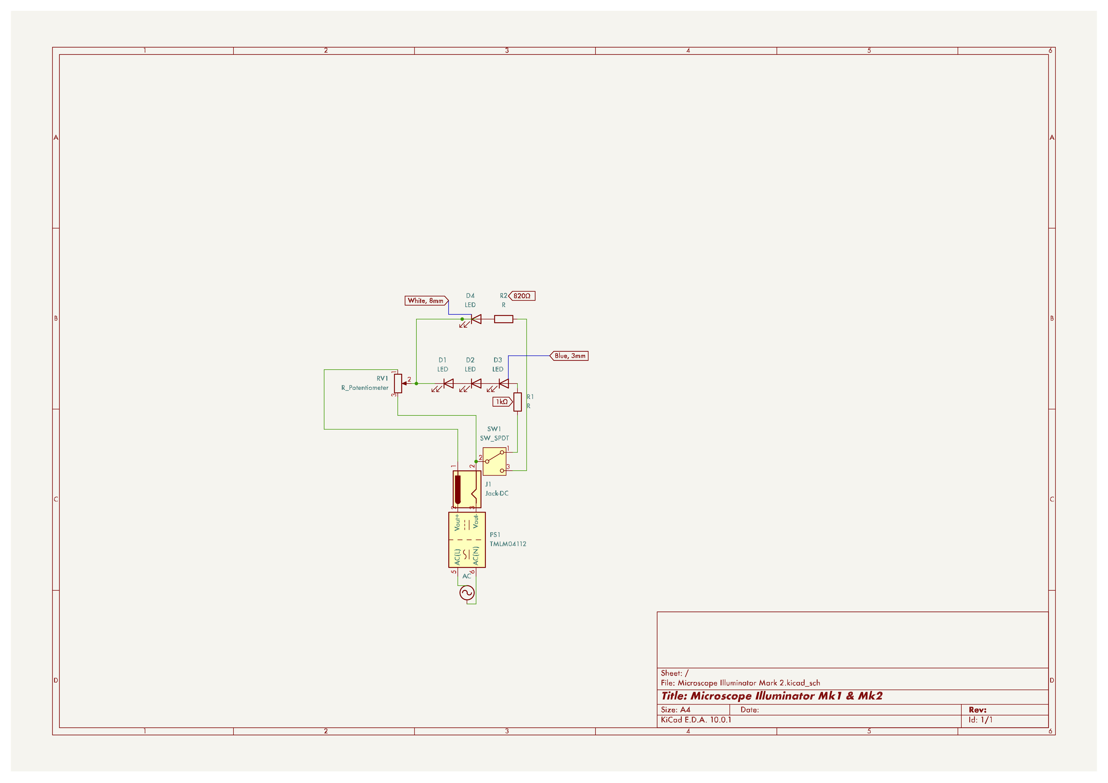
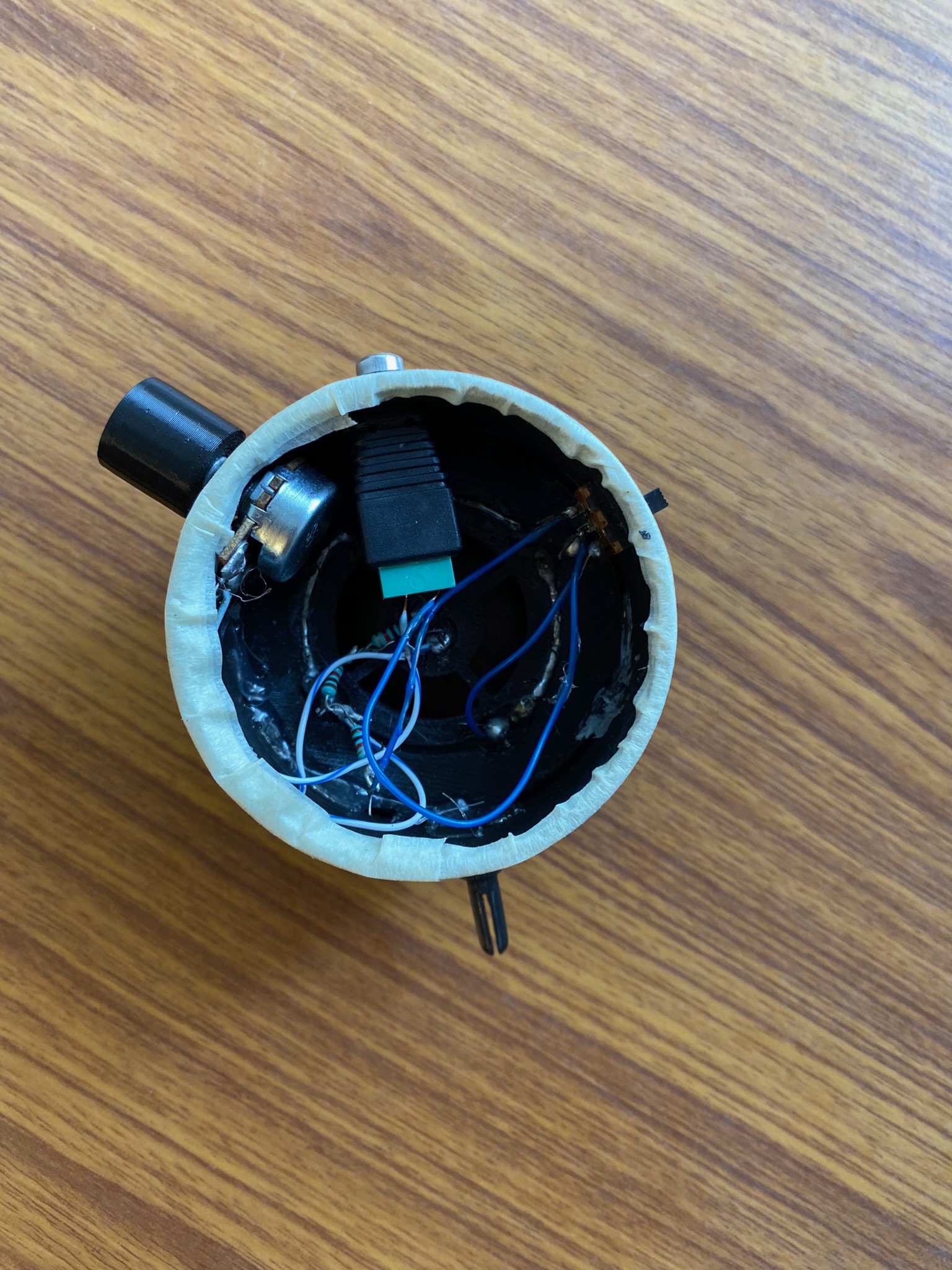
Based on the requirement for two colour modes, it made sense to create two parallel circuits: one supplying the white LEDs, and one supplying the blue LEDs. The mode could be switched using a 3-way selector switch. To remove the hassle and wastefulness of batteries, I decided to power the illuminator using a standard DC input jack. I included a 10K$\ohm$ potentiometer to use as a dimmer.
Testing the dimming mechanism
3D Model & Construction
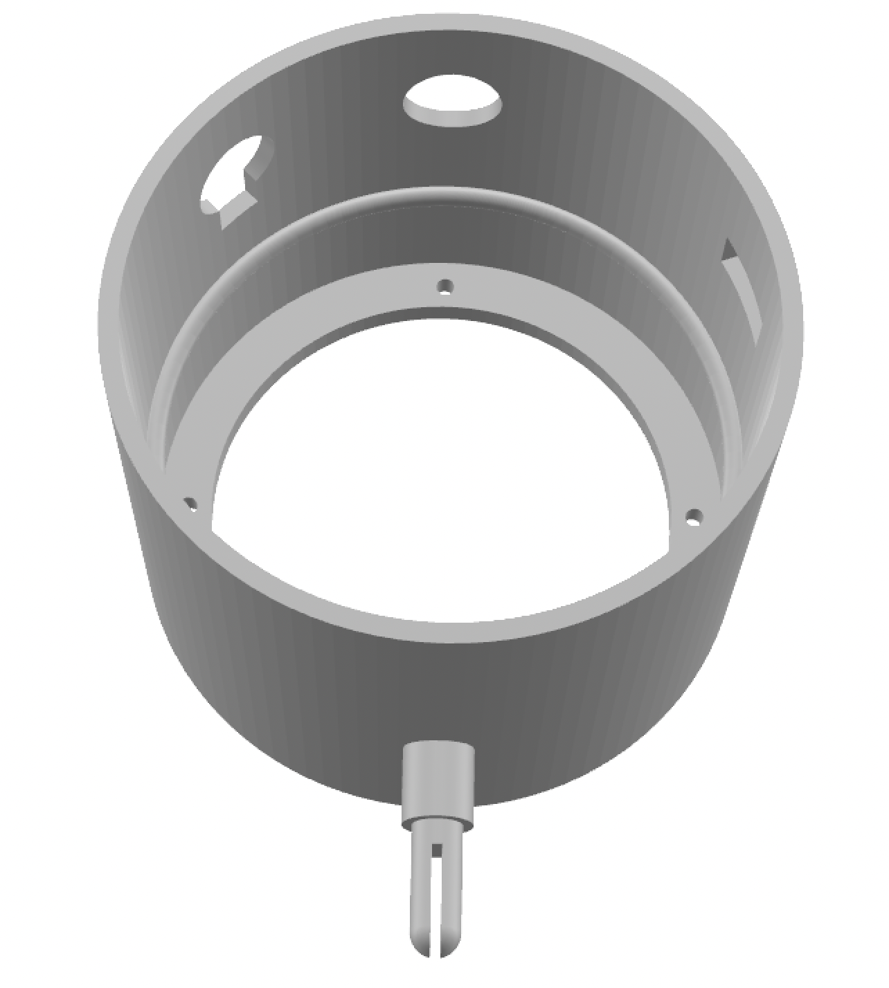
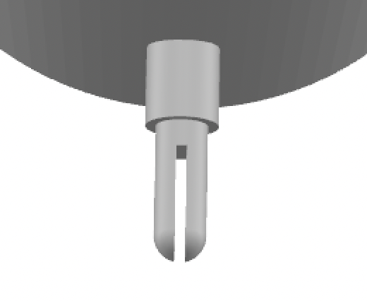
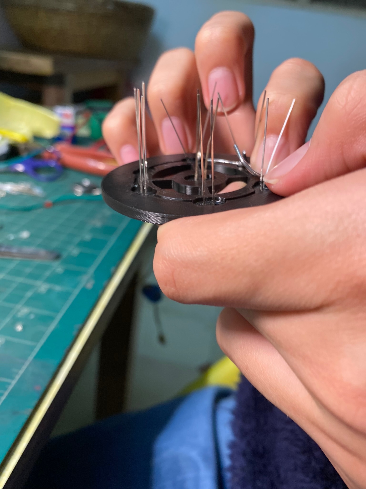
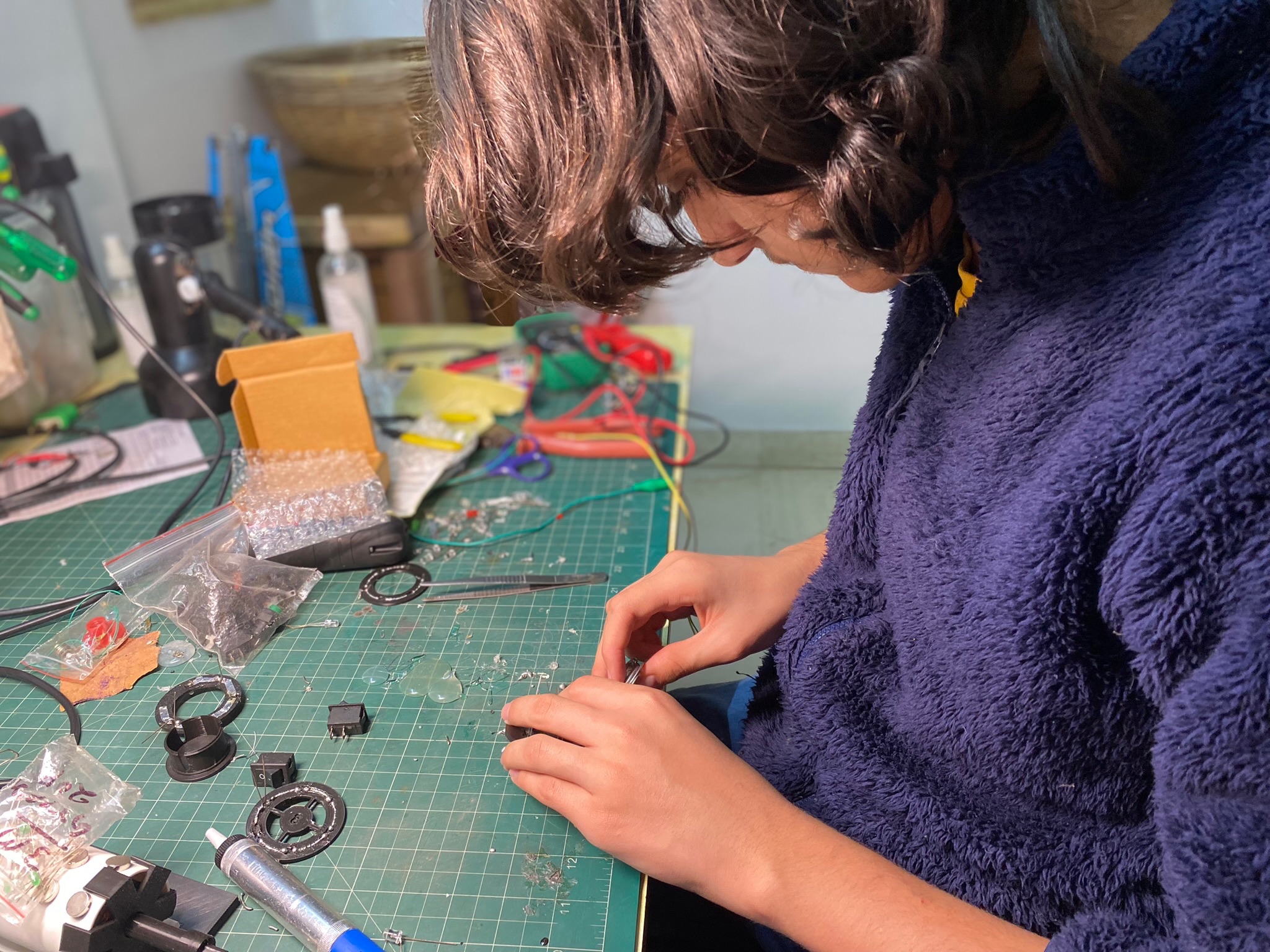
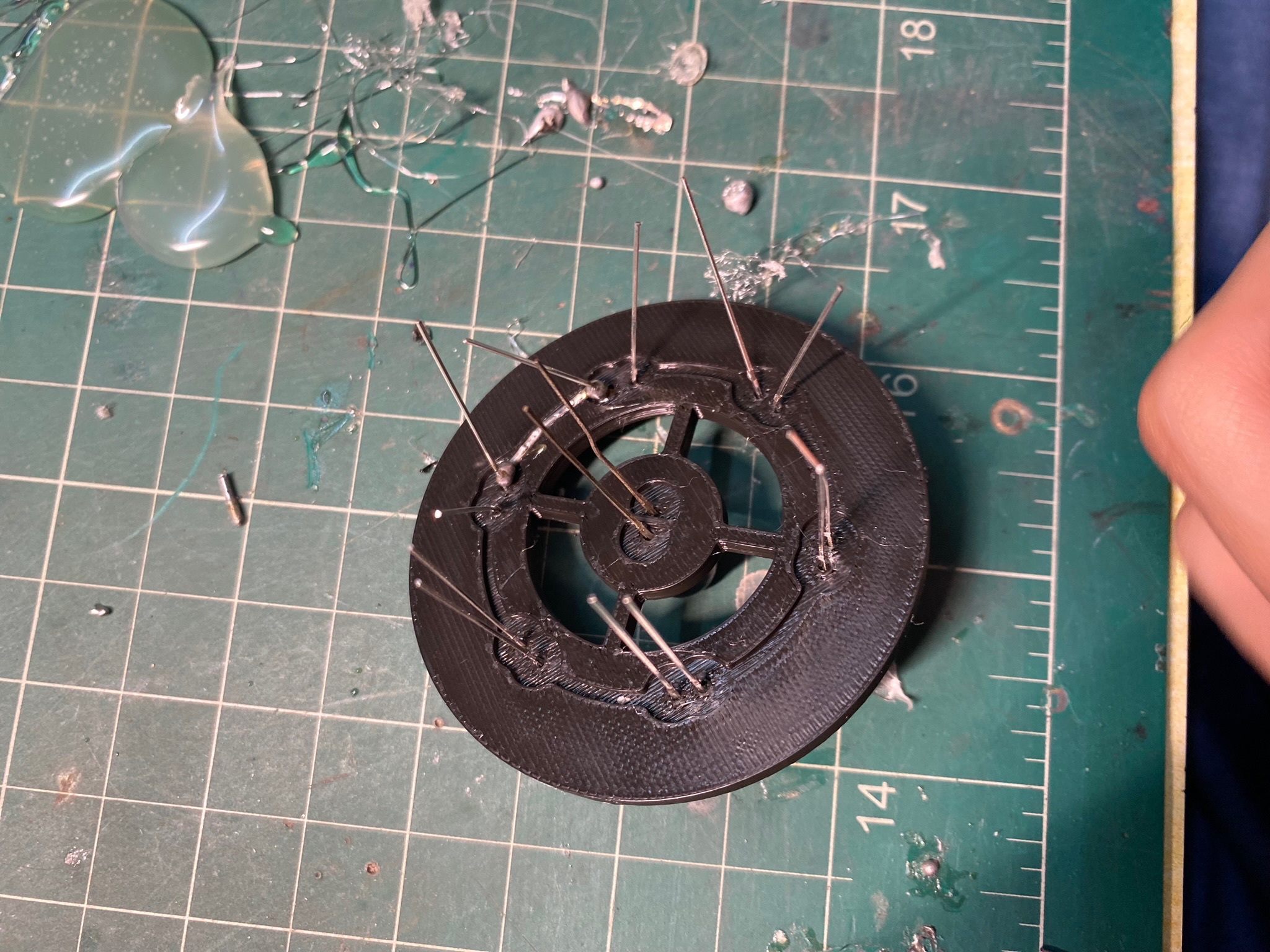
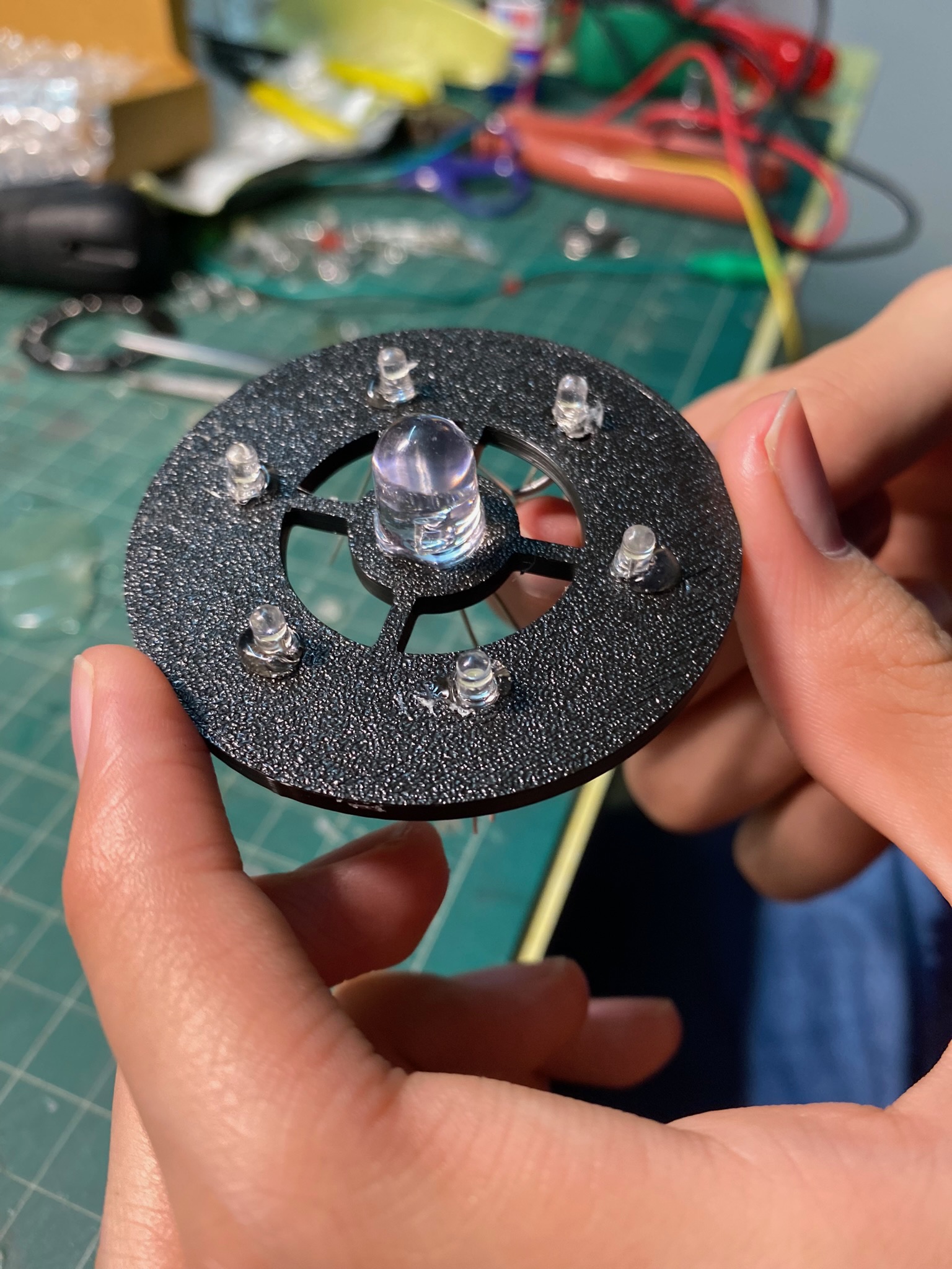
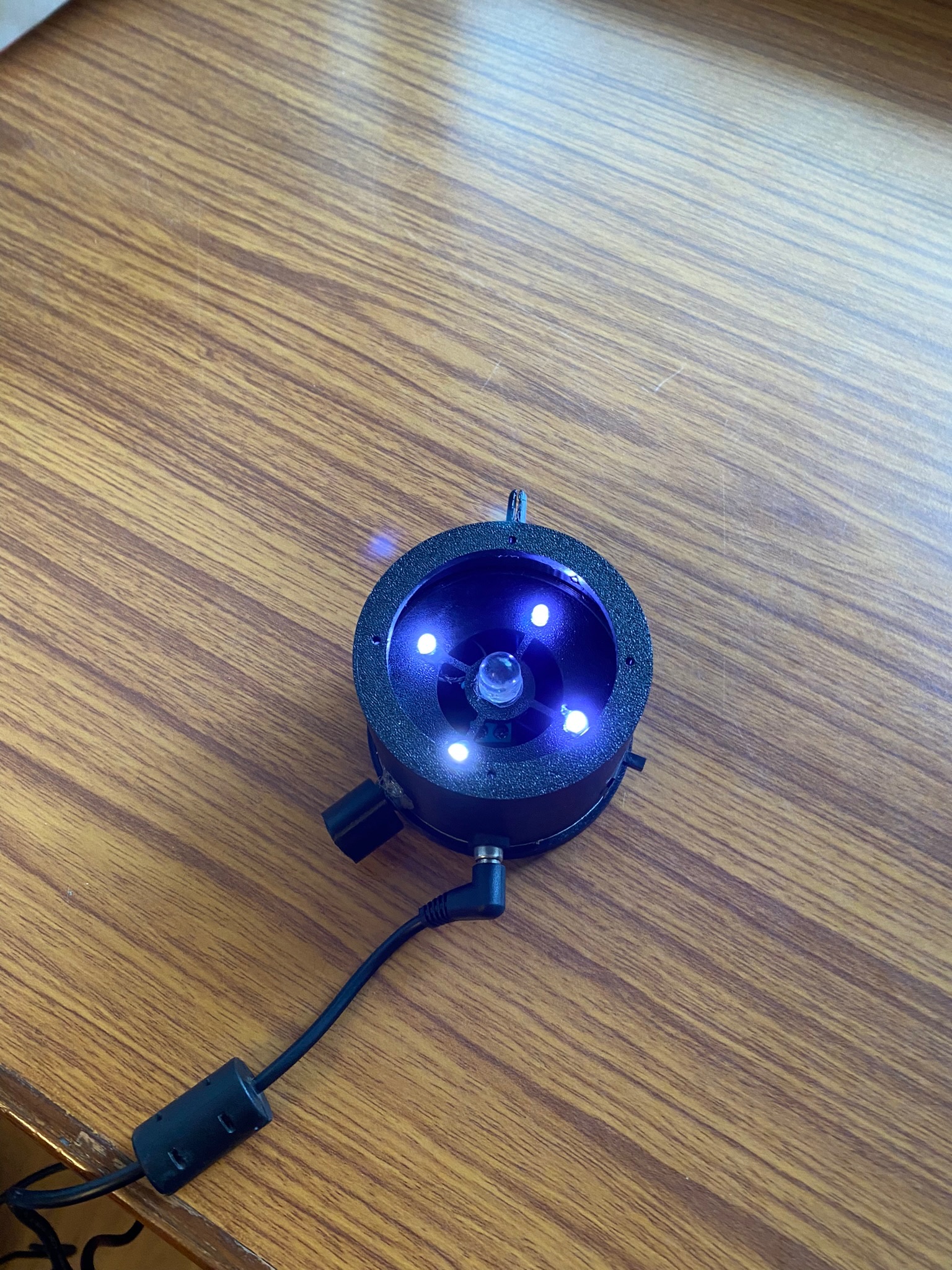
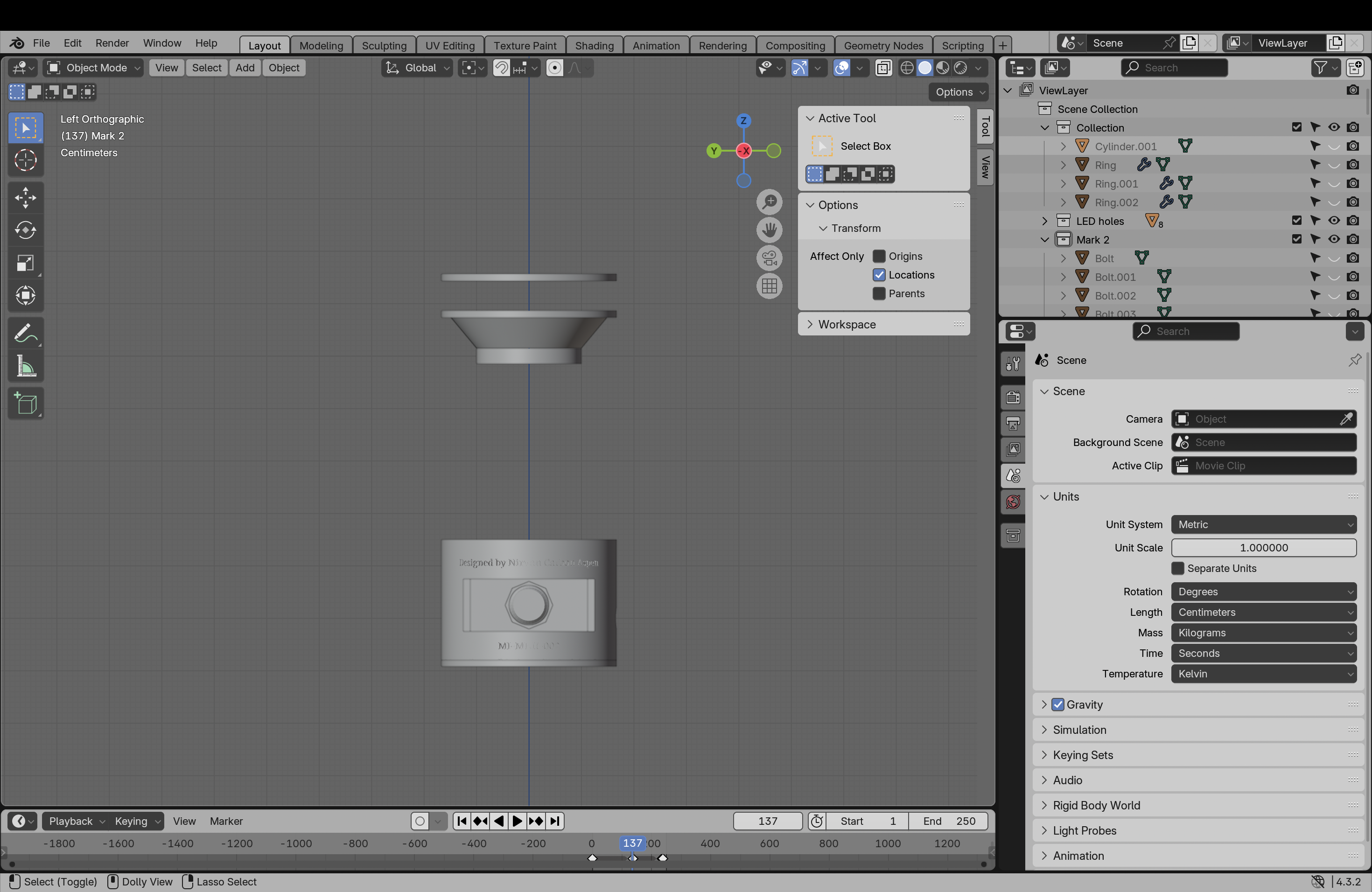
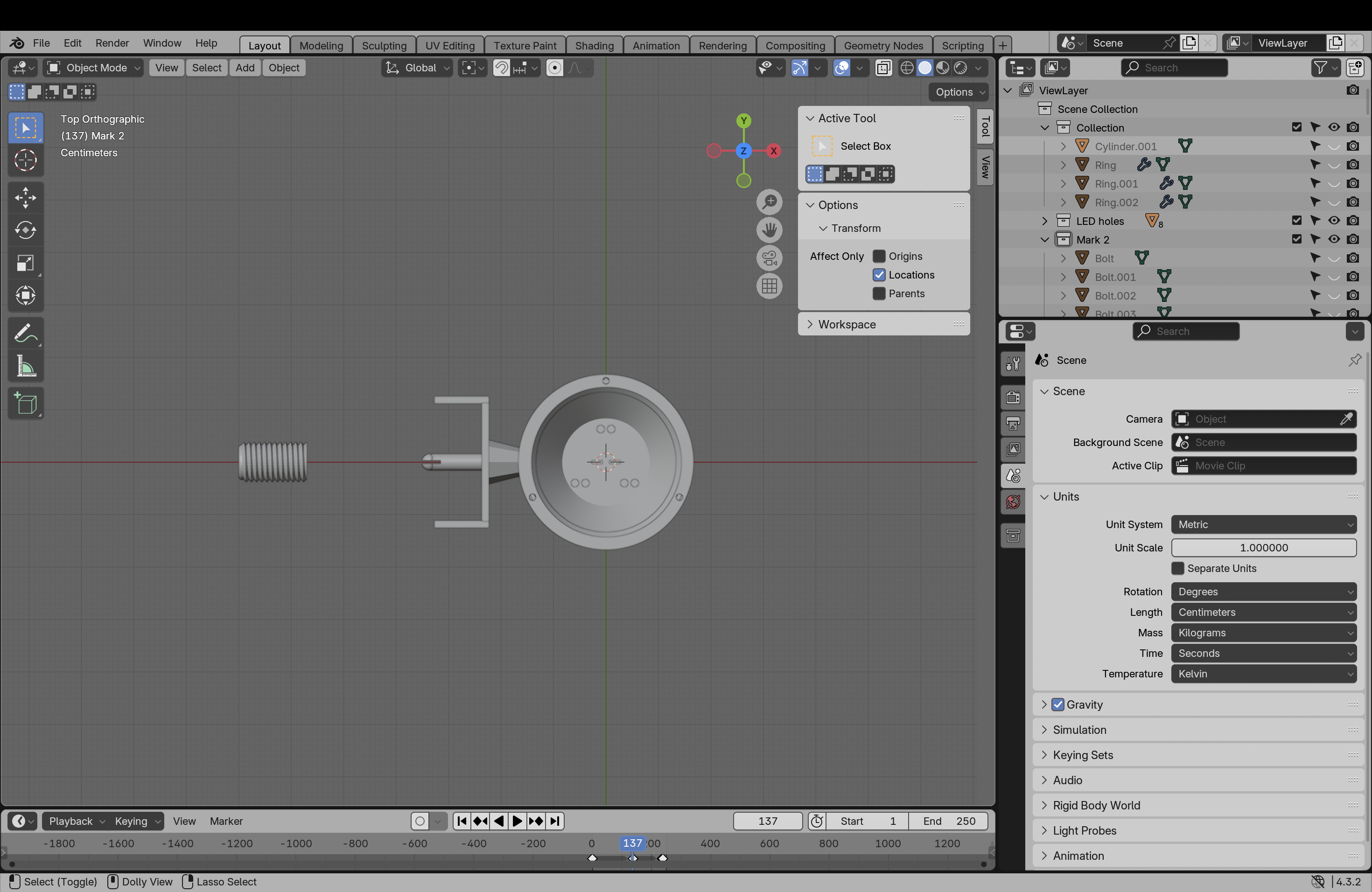
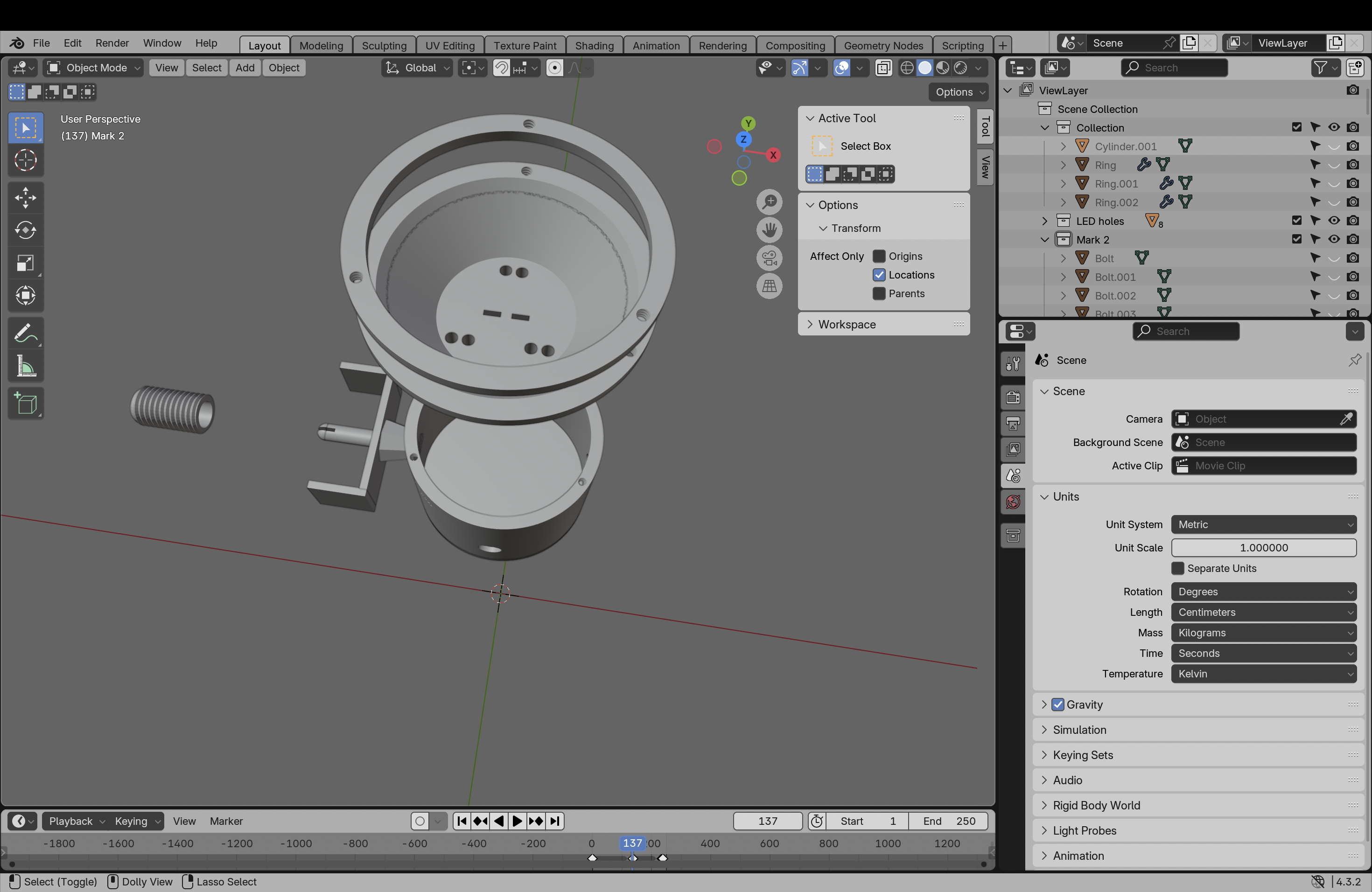
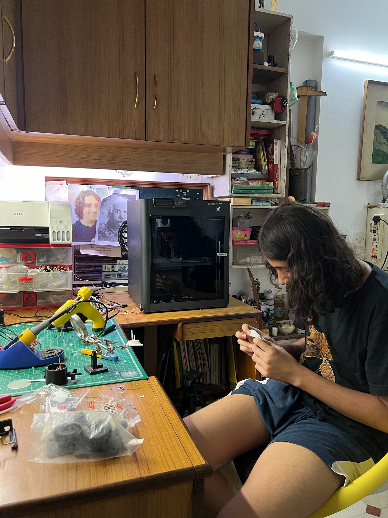
I designed the 3D model in Blender. The main circuitry was housed on a singular 3D printed “plate” which had grooves for solder “wiring” - essentially my 3D printed version of a PCB.
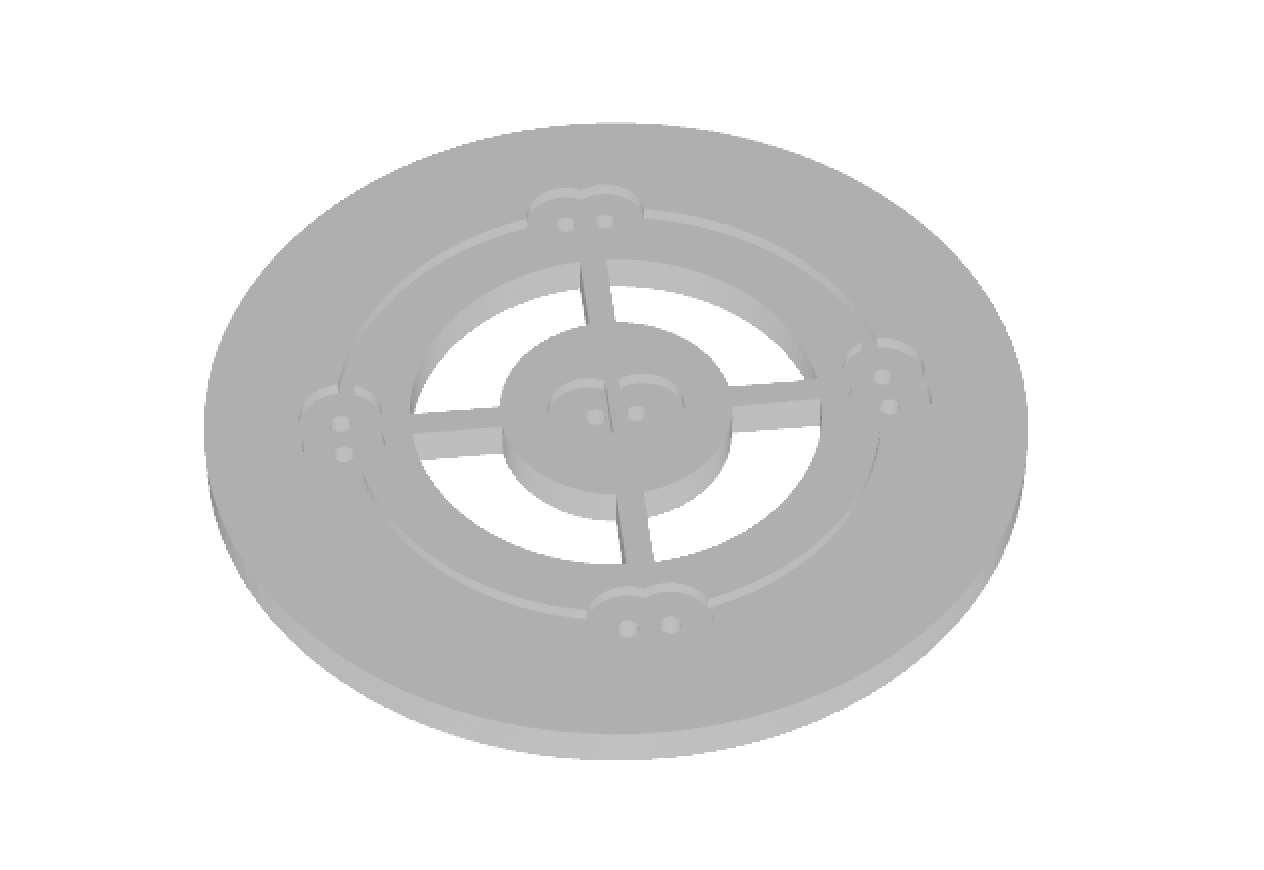
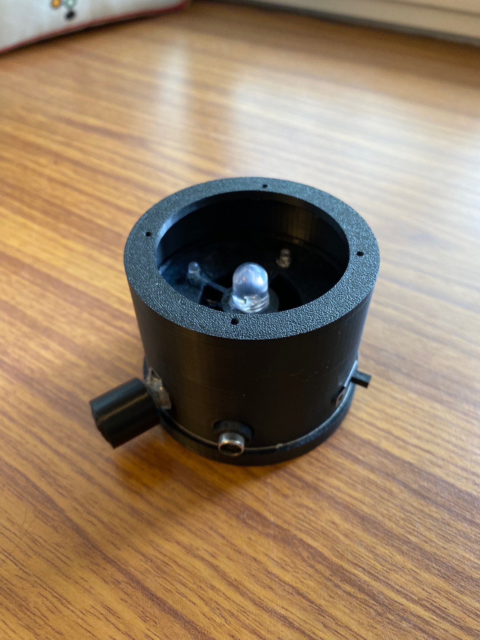
With this design, I could solder and assemble the wiring comfortably, and then fix this entire electronics unit in place in the large outer casing.
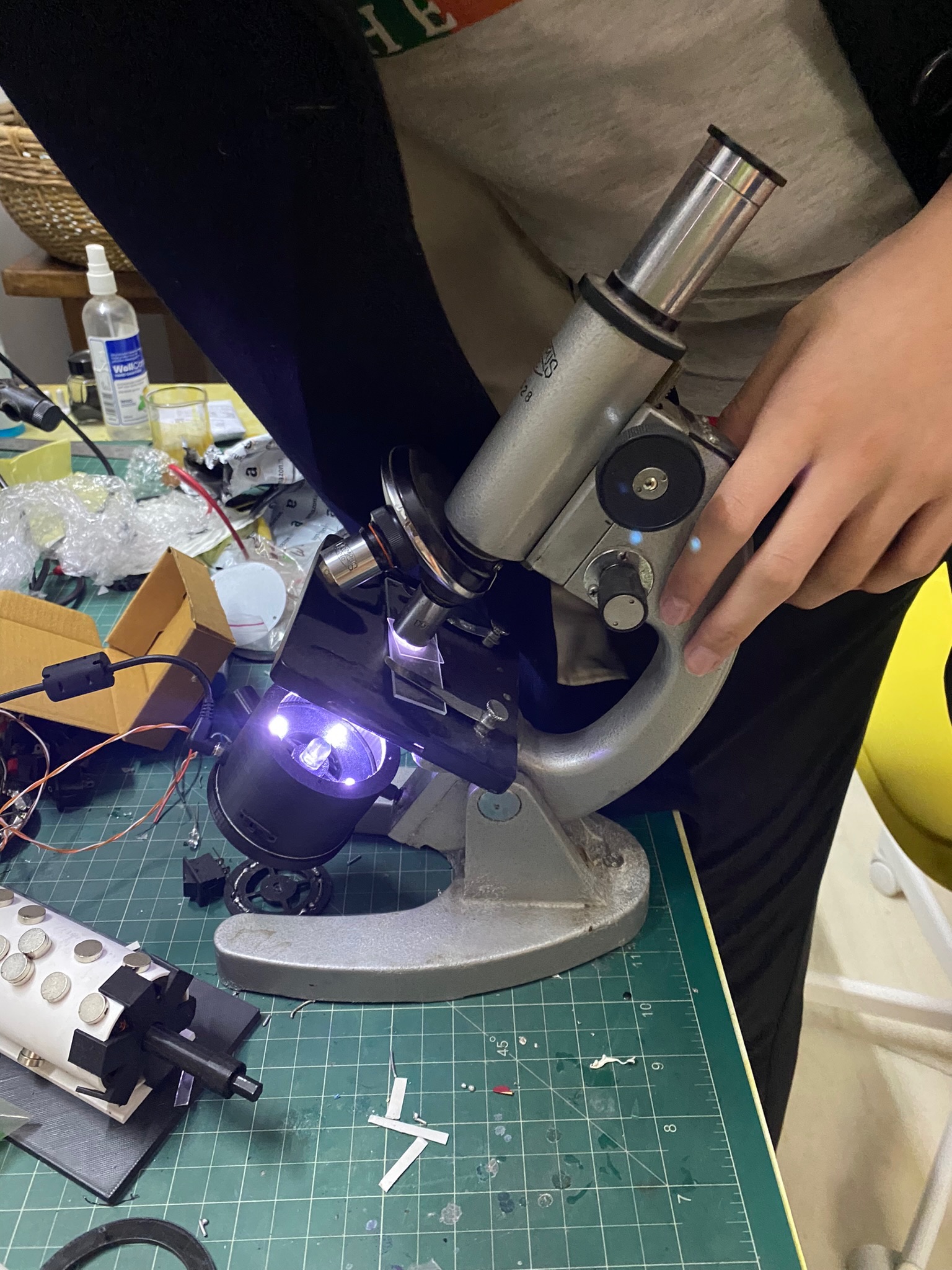
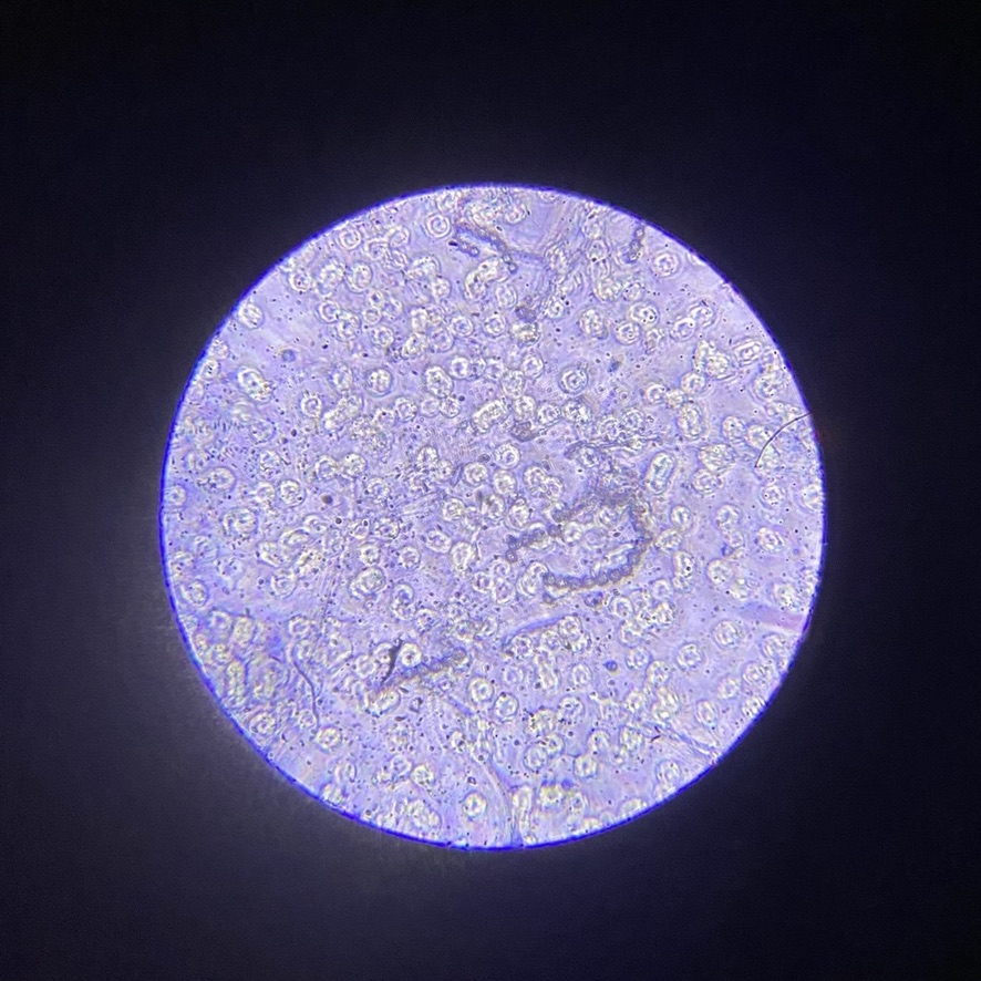
Results
MK-II
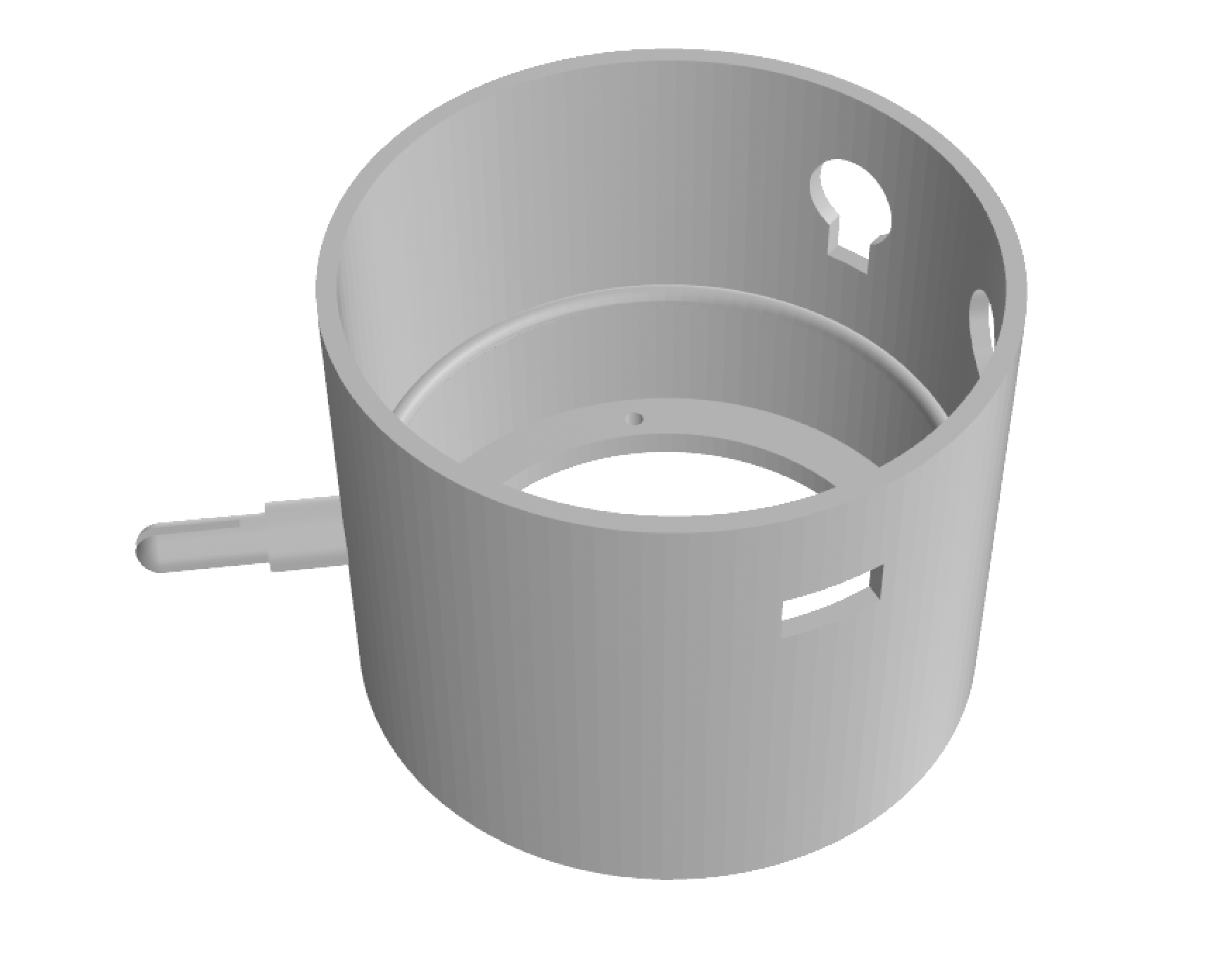
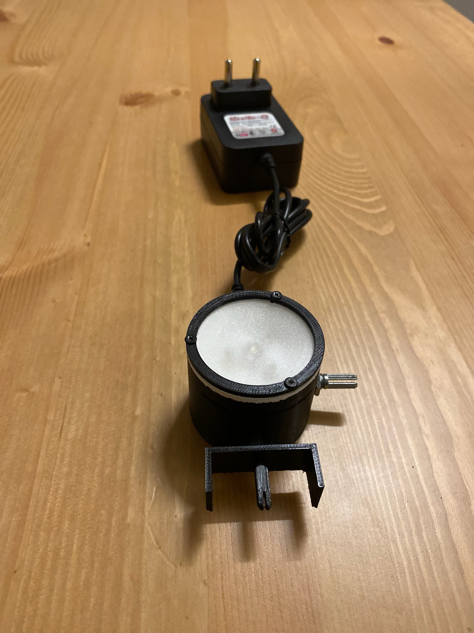
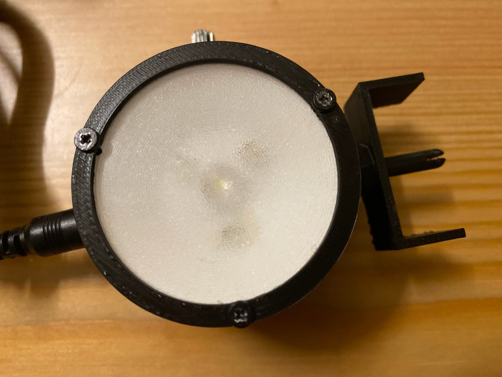
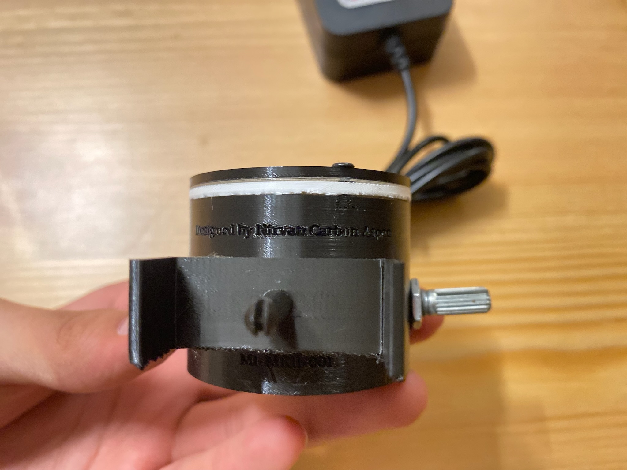
The MKII did not change significantly in terms of circuitry - it’s major improvement was in the physical design, since it had a smaller form factor. The MKII arose out of the need to attach similar compound monocular microscopes in my school with the illuminator: after showing it to my biology teacher, she was very impressed, and asked me to fit some of the microscopes in school which also had only mirrors as illumination sources. Unlike my microscope, the ones in school had a condenser before the stage, and the MKI was too bulky to fit.
3D Model & Construction
The main goal was to make the illuminator smaller, and more rugged - it needed to survive in a school environment. I thus proceeded to redesign the entire interior.
Results
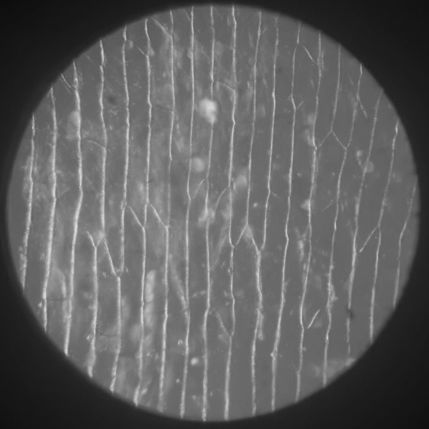
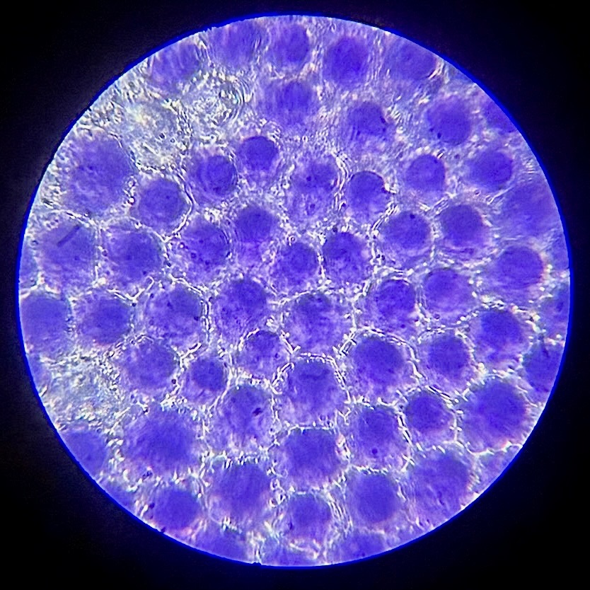
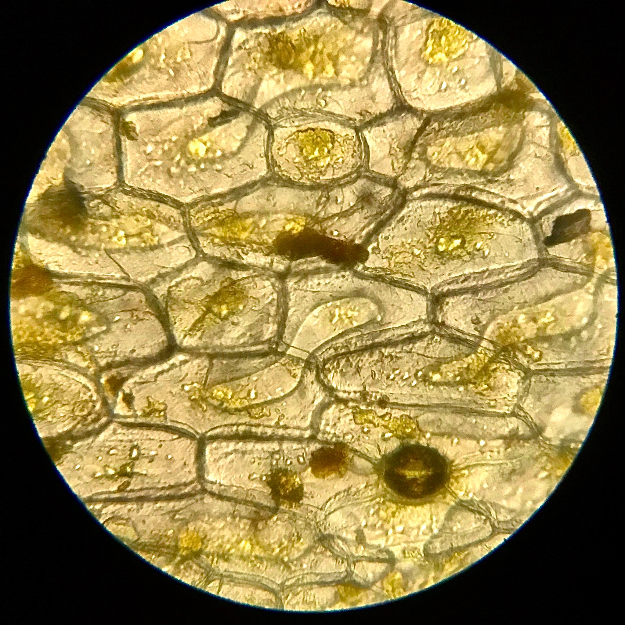
Fig. 2 and Fig. 3 are both results from using this illuminator in school.
MK-III
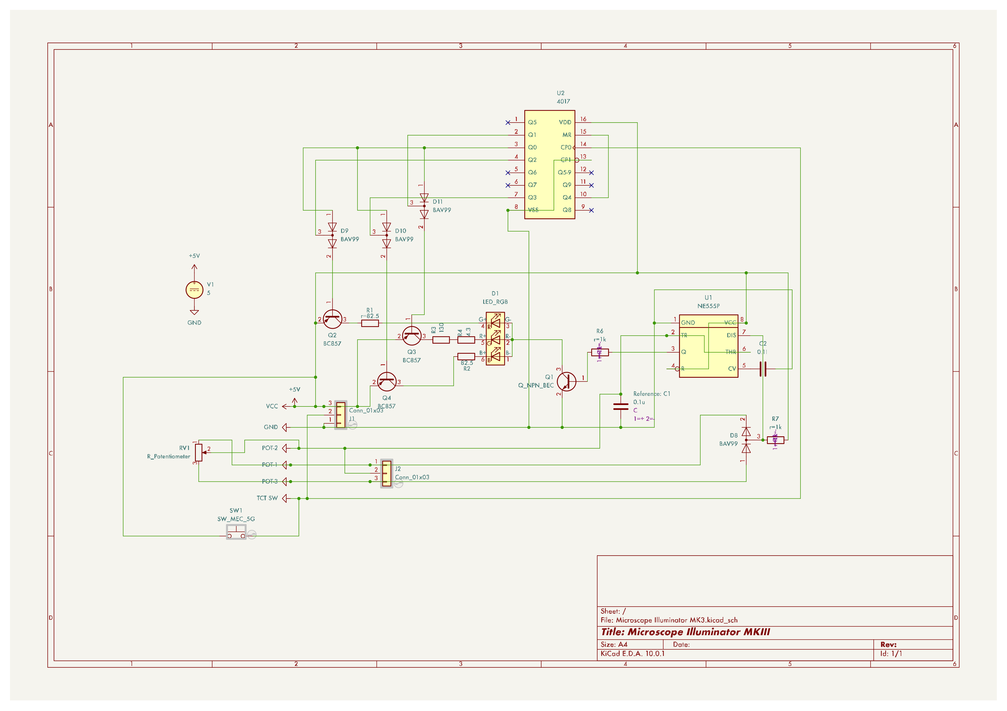
I have not yet made the MKIII. The main concept behind the MKIII was further optical advancement. It would feature individual R, G and B LEDs that could be turned on and off. This provided two advantages - firstly, images could be taken of the same sample with illumination from each colour (R, G, B), and then those three images combined. This provides better contrast, higher resolution, and less chromatic aberration in the images. Secondly, individual colour illumination provided exciting opportunities for applying colour theory to experiment with different stains and how different coloured illumination could provide different results.
The potential of the illuminator is enormous: it can revive an outdated, almost defunct piece of equipment for approximately INR 500. For anyone anywhere with this style of microscope, it can serve to transform a vague collection of dim lines into something real - an actual cell (instead of a textbook diagram), a real moving tardigrade, or anything else one chooses to observe - bringing science one step closer to home. Because despite everything, nothing makes something feel more real and true than seeing it for yourself. And after all, at its core, that’s what this illuminator is about.