Tesla-Inspired Alternator
Of the many things impressive about Nikola Tesla, most impressive to me is his creativity and imagination. He is, in many ways, a character straight out of science fiction, daring to imagine and actually invent seemingly impossible devices, the lasting impact and benefit on the human race of which is quite immeasurable. The fact that he died in poverty, and mostly unacknowledged for inventing things which we survive on today, is upsetting to me, and thus at every opportunity I get, I find myself advocating for his greatness and telling people about him.
At this time, I was excitedly learning more about electromagnetism. Having started reading Tesla’s diaries and looking at his drawings, I wanted to get hands-on and myself build a small alternator.
The basic idea was simple - take a cylindrical rod, wrap a whole bunch of copper wire around it, place it inside a hollow cylinder lined with magnets, and spin the rod really fast. In practice, of course, there were a few challenges to tackle.
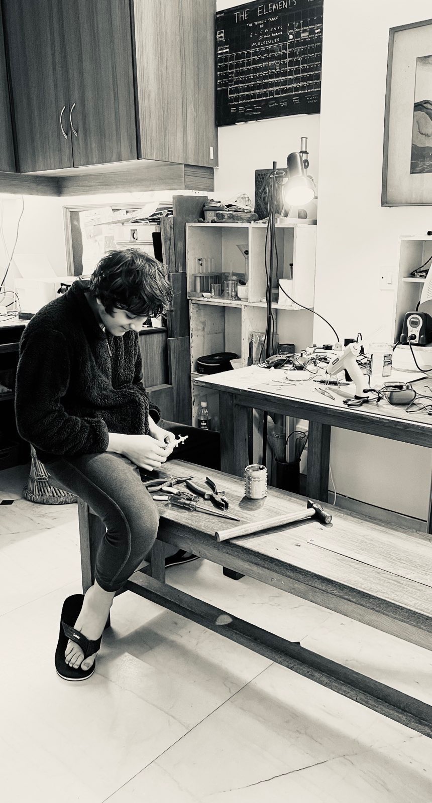
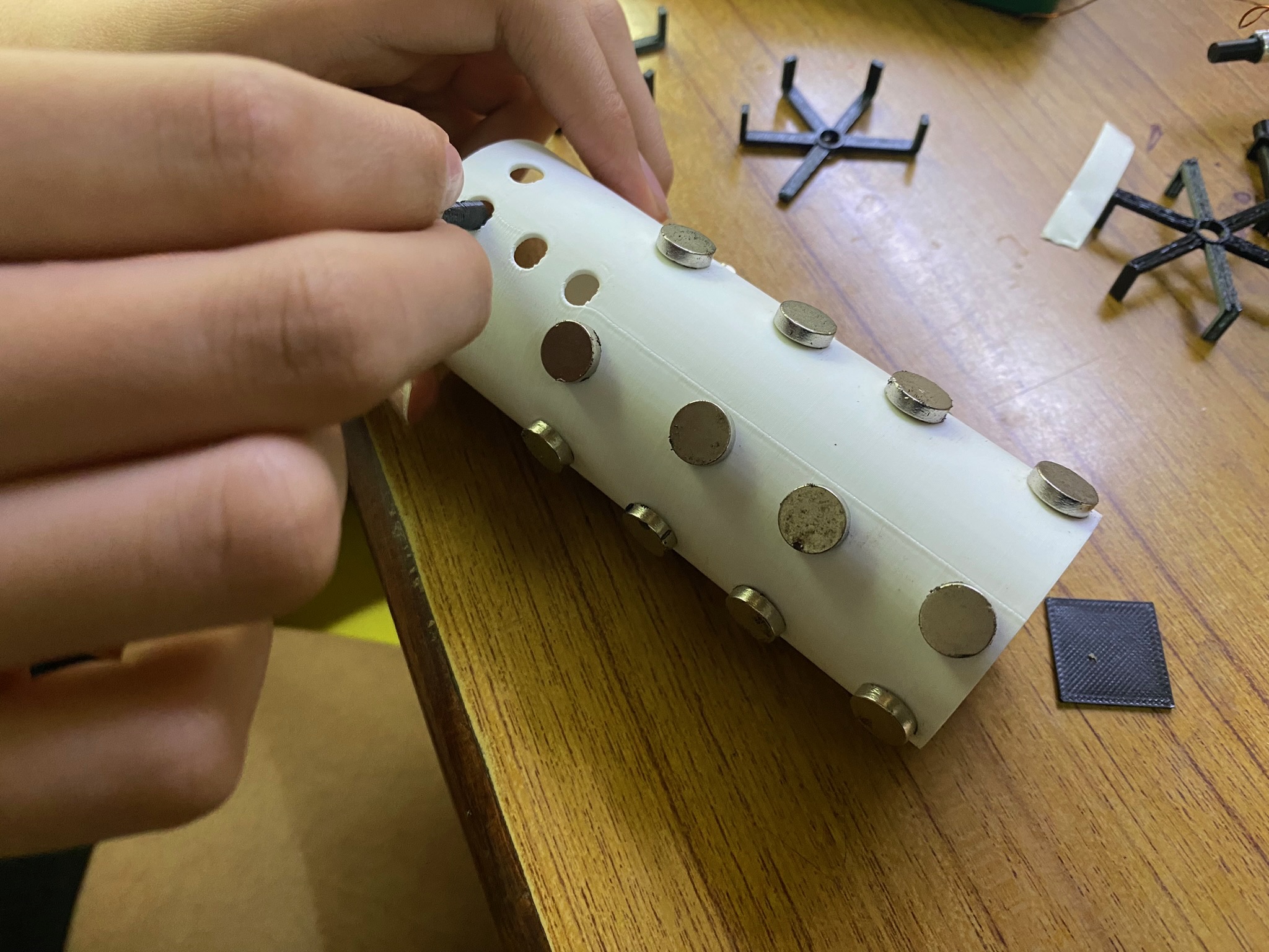
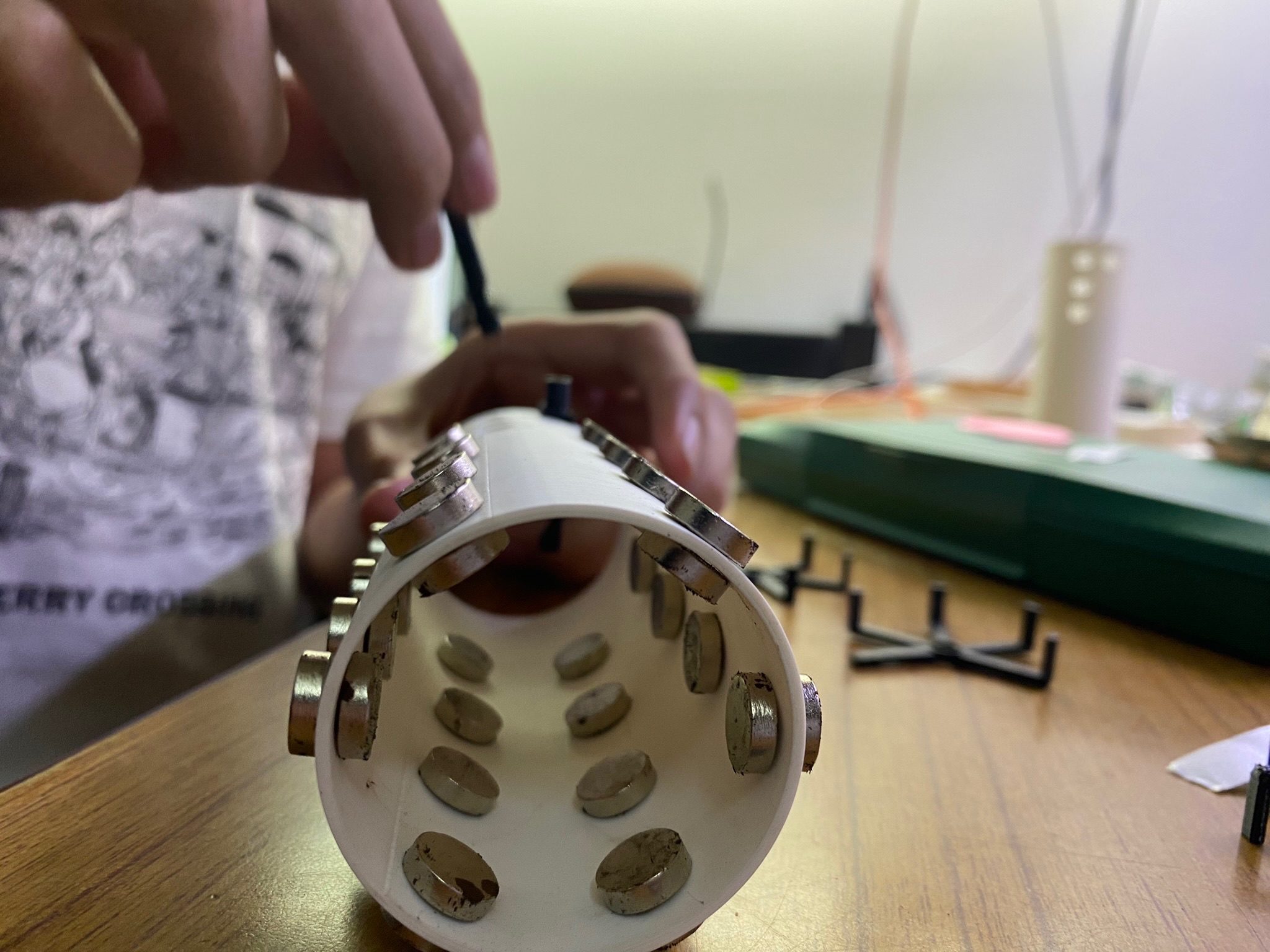
The first challenge I faced was the kind of problem that only really makes itself known when you actually start building something. I had chosen a discarded aluminium can to be the main body, and it was quite narrow - one really couldn’t get a hand to fit inside and place the magnets in the right positions. I didn’t want to cut the can along its height and then re-glue it, since that would compromise structural integrity. Additionally, my primary method of sticking anything at the time was using my trusty hot glue gun - and I was worried that the heat would significantly affect the strength of the neodymium magnets I had got specially for this project. So instead of having magnets stuck to the inside of the can, I decided to put magnets on both the inside and outside of the can. I was very satisfied with this solution, because it allowed me to position the magnets simply by dragging the magnets on the outside of the can. This meant I could also add more magnets to the magnet “stack” on the outside, increasing the magnetic flux. The entire system was modular.
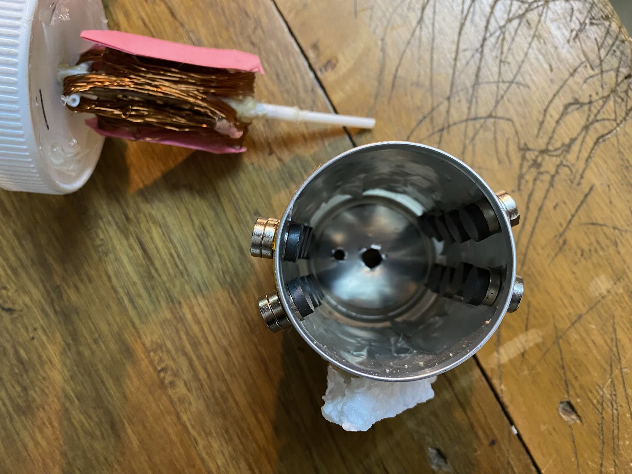
Since by Faraday’s law of electromagnetic induction: $$\mathcal{E}=-\frac{d\Phi}{dt}$$(where $\mathcal{E}$ is induced potential and $\Phi$ is magnetic flux), and since $\Phi=BA$ (where $B$ is magnetic flux density and $A$ is area): $$\mathcal{E}=-B\frac{dA}{dt}$$ I did not simply wrap a lot of copper wire along a plastic tube. Instead, I glued small plastic pieces protruding at right angles, and wrapped the copper wire around those - this increased the cross sectional area of the rotor assembly, and hence when the rotor rotated, $dA$ was greater, which in turn led to an increase in the induced potential.
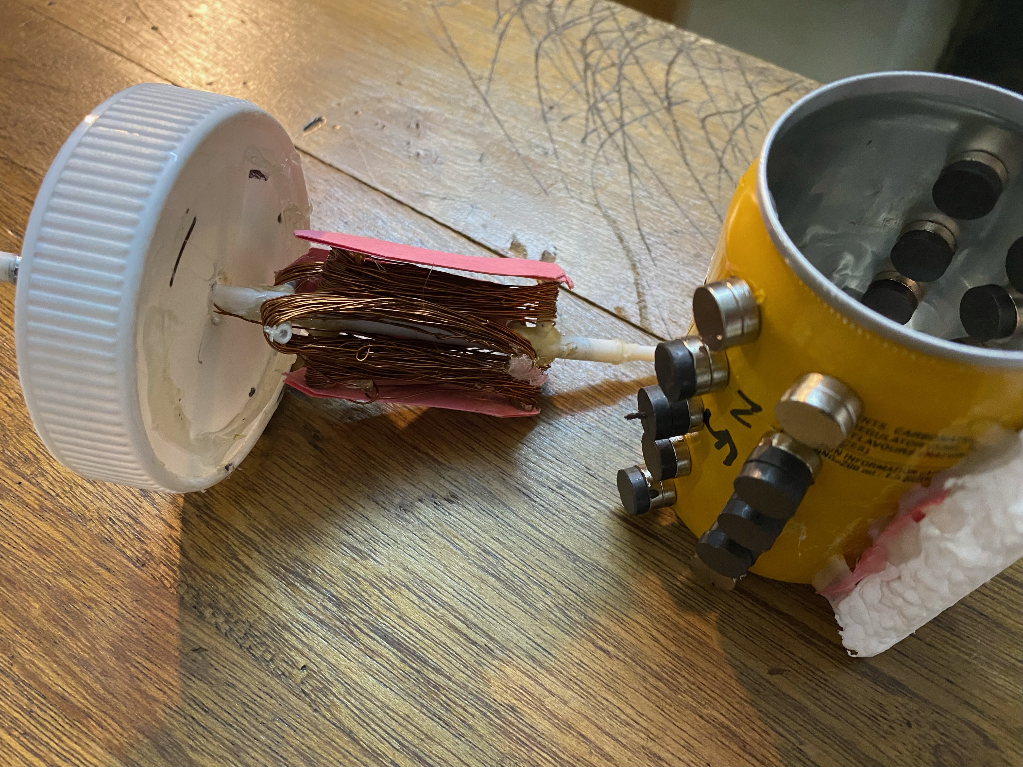
One of the biggest hurdles was designing the slip-ring and brushes mechanism - the part of the alternator that ensures continuous electrical contact between the rotating rotor assembly and the stationary platform. Usually on a commercial scale, this is done using carbon (graphite) brushes and metal slip-rings attached to the rotor shaft. I had neither sufficient graphite (since the graphite wears down, and the brushes need to be replaced frequently) nor metal rings, so I ended up using conductive tape stuck to the rotor shaft as the slip rings, and metal hooks as the brushes.
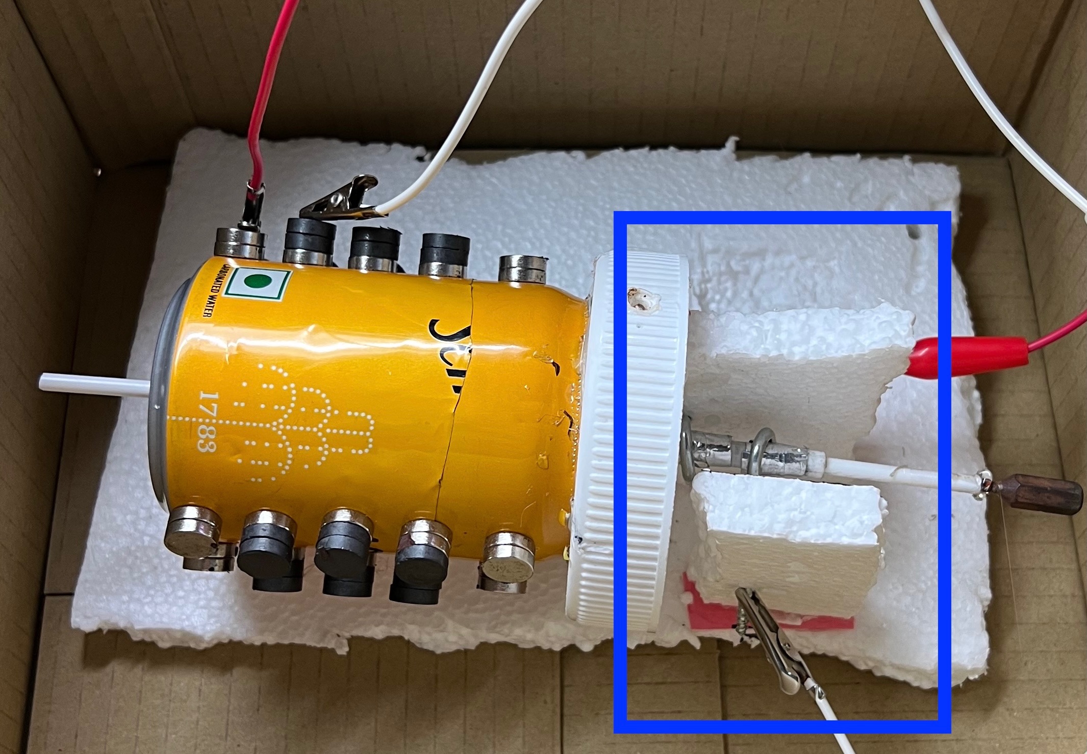
When I first spun the rotor (by hand) after the whole alternator was finished, the multimeter display was completely unchanging. I then switched to using a motorised screwdriver to provide a faster, constant rotation - and this finally produced a measurable output of around 6-12mVAC. Success!
I demoed this project on National Science Day (28th February 2023) at school, and won the first prize.
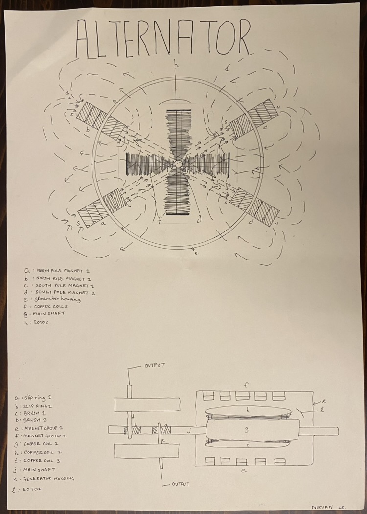
Embodying the true spirit of Tesla, I hand-drew a technical diagram of the alternator using beautiful rOtring ink pens:
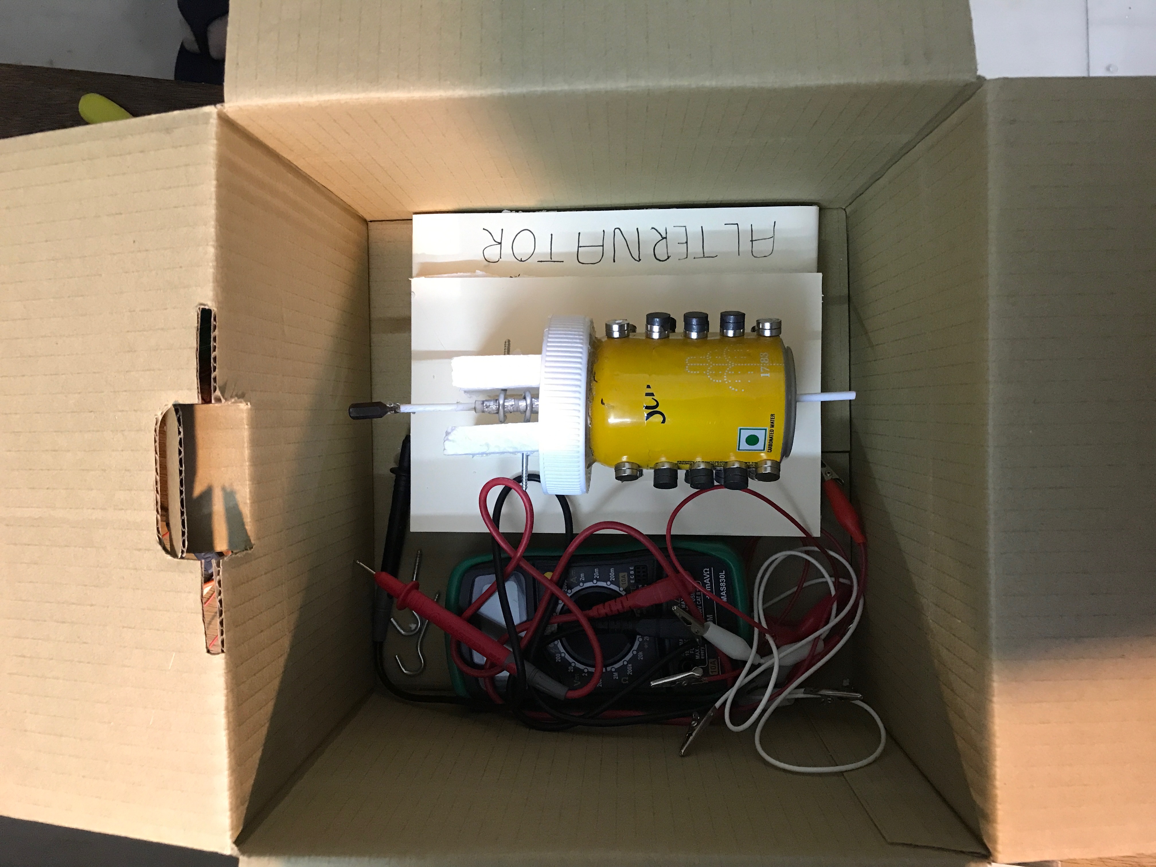
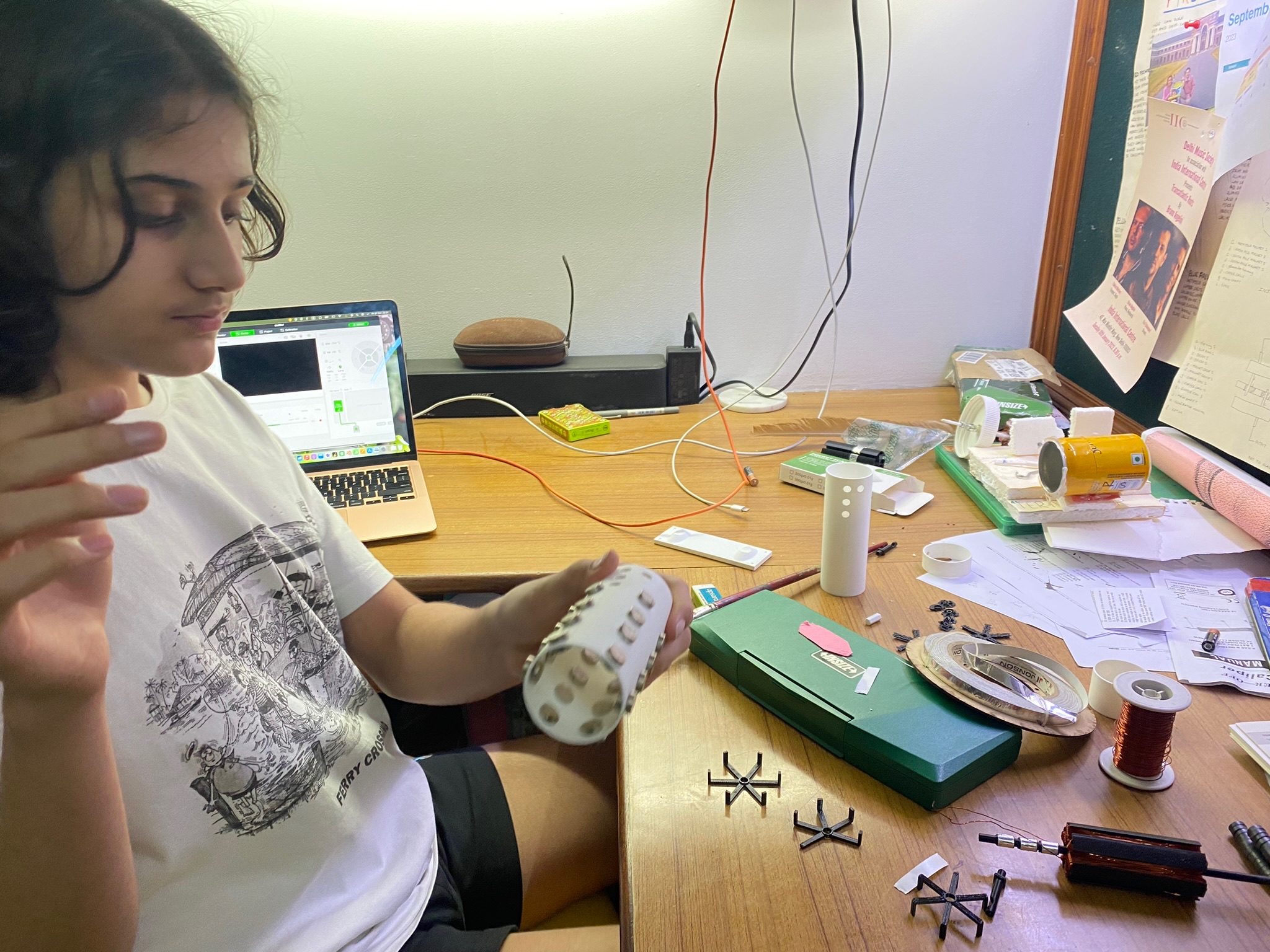
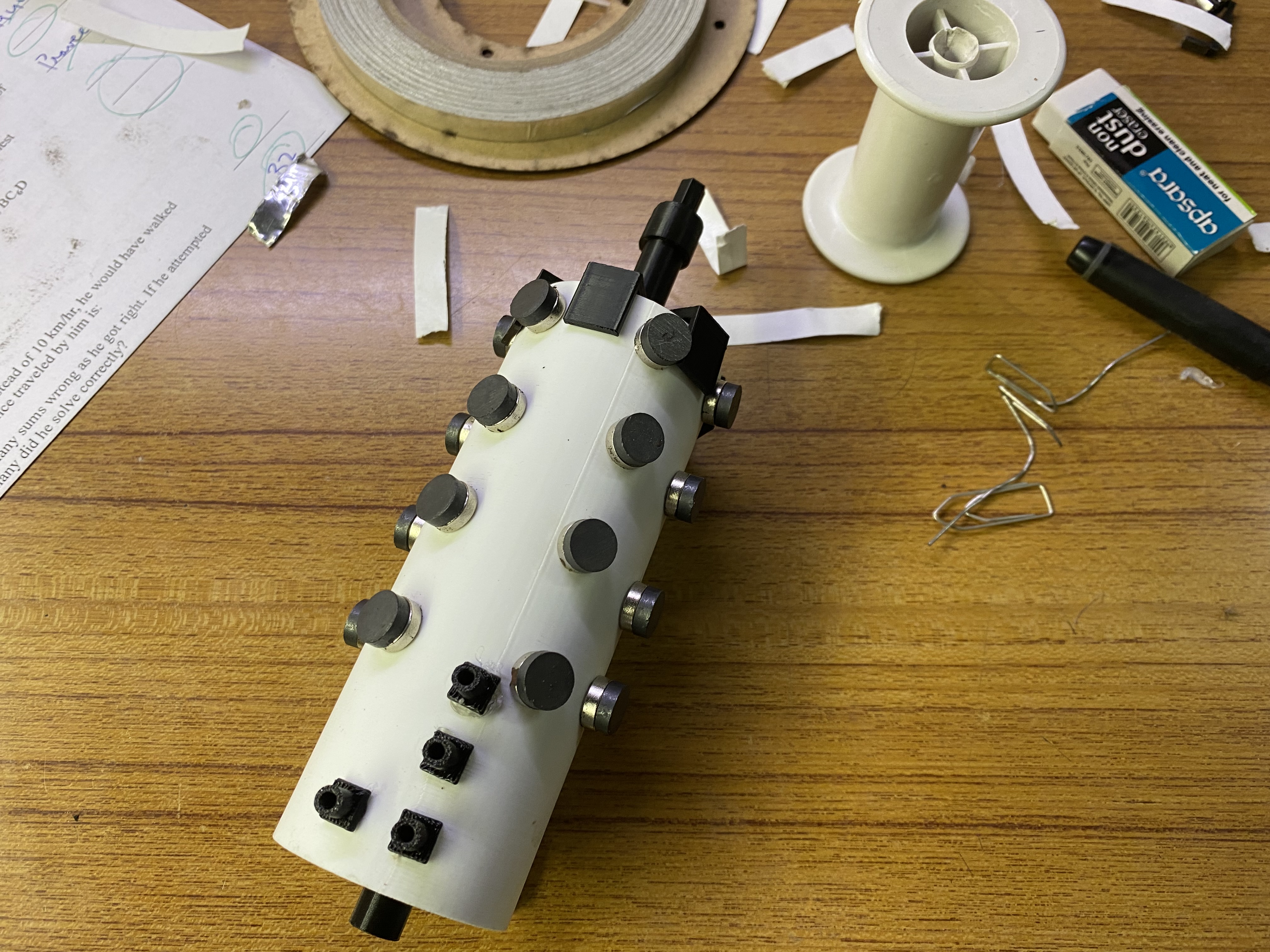
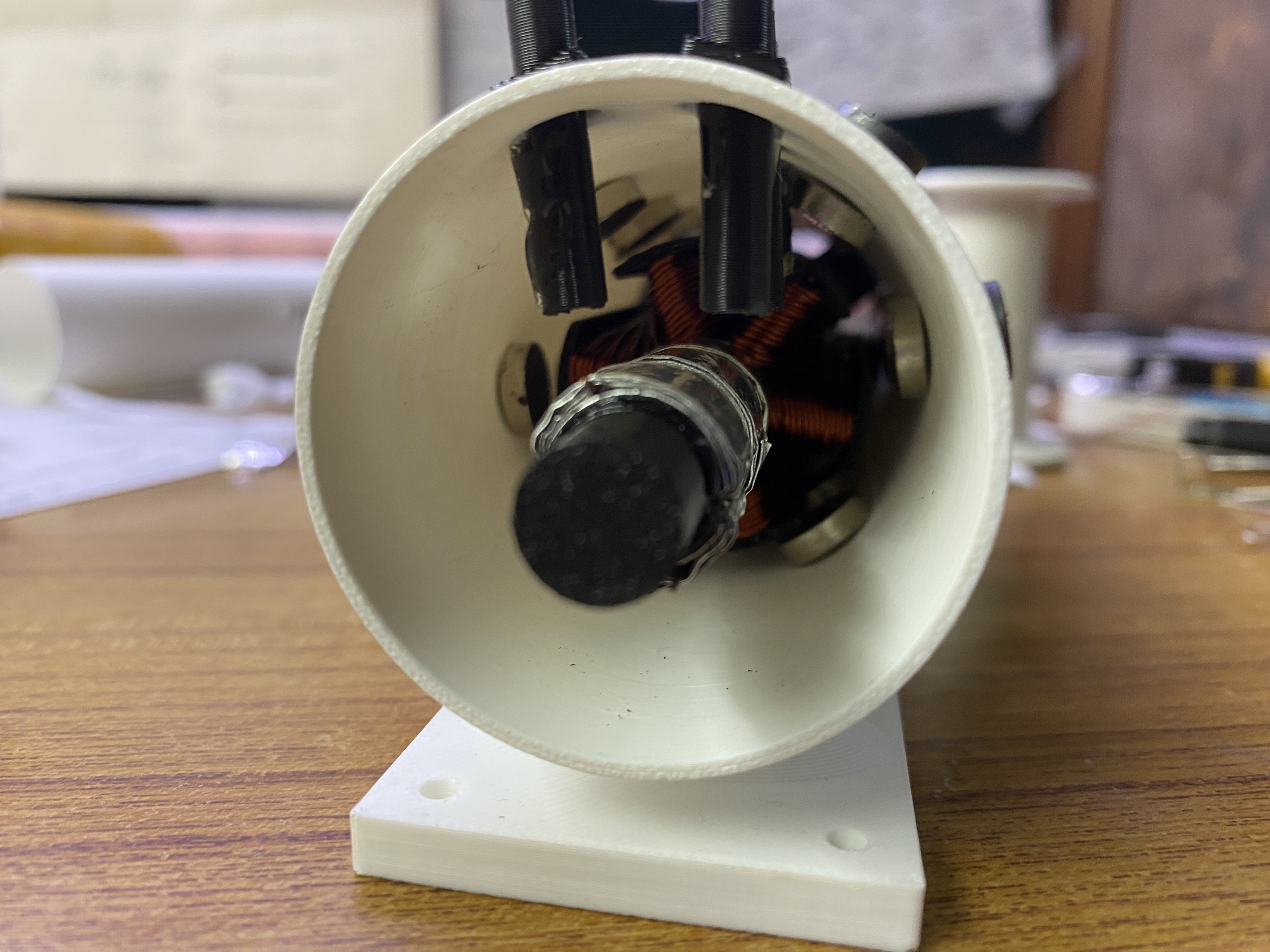
Later in the year, I got a 3D printer. I took this opportunity and improved my alternator - both in terms of the magnitude of induced potential, and the structural stability.
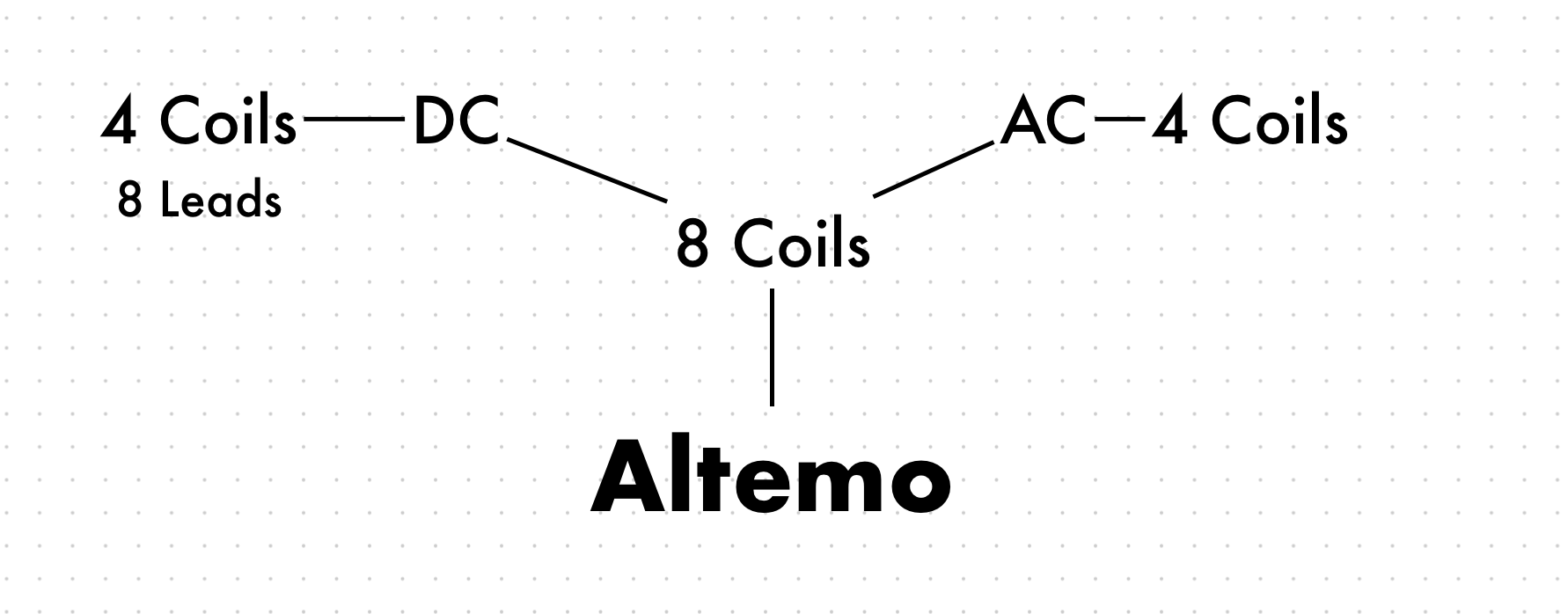
However, what I ended up making wasn’t simply an alternator - it was what I called an “Altemo”. It produced both AC and DC output, since it had some coils attached to slip-rings, and some coils attached to a commutator. It produced approximately 15-21mVAC (I do not remember the DC output magnitude). I switched from using hooks as brushes to unfolded paper clips, since they were more malleable, and I could shape them more easily.