After watching the movie October Sky in 2021, I told my father, I want to build a rocket. Thus began a three year long project that would be one of the most exciting and complex ones I ever undertook.
After some preliminary research into propellants, we came across sugar rockets. These seemed to be the best choice, since the ingredients were widely available and it would (hopefully) be safer than boiling alcohol on a bonfire (this is a scene in October Sky).
Initially following certain articles as guides, we were using a specific size of PVC pipe as the rocket body. As we did more research, we moved away from one specific article and began to trust our math more (we made a spreadsheet to calculate the rocket’s trajectory). Eventually, we did away with the PVC pipe altogether, instead opting to custom print the rocket body. This enabled us to greatly improve the design of the rocket.
The spreadsheet (model) went through many iterations (at least 20!). For two years, we were researching materials, propellants, body shapes, and the like, absolutely perfecting the theoretical model.
Sucrose Series
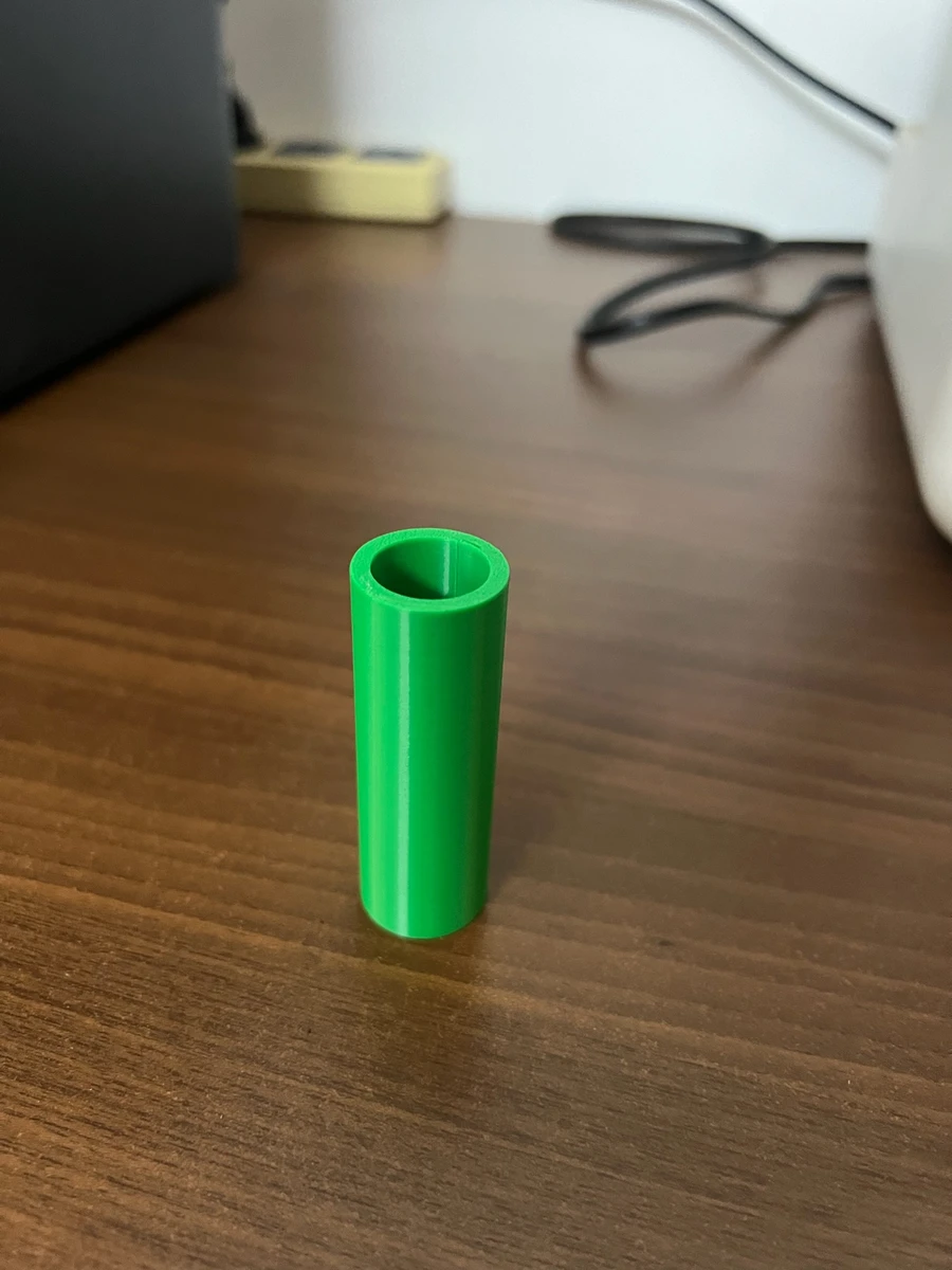
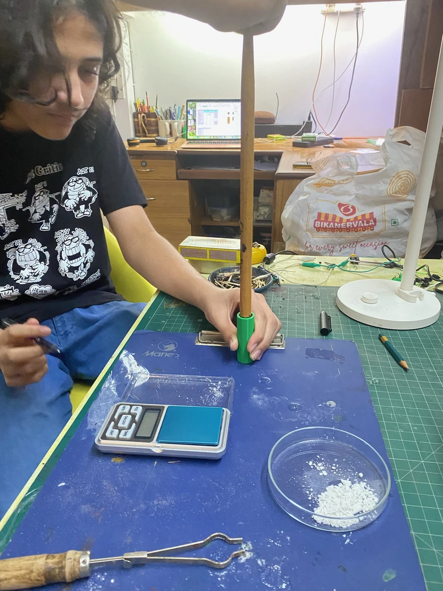
Eventually, in October 2023, I finally had all the materials together (and a finished theoretical model) to put the actual rocket together. The first rocket series was nicknamed Sucrose, after the fuel the propellant was using. I used a 35-65 mixture of powdered sucrose and potassium nitrate for the propellant. The body was simply a 3D printed tube, capped off with putty on both sides. I used a drill bit to manually drill the nozzle into the propellant.
The chemical equation for the combustion of the propellant is: $$C_{12}H_{22}O_{11}+6.288KNO_3\rightarrow 3.796CO_2+5.205CO+7.794H_2O+3.065H_2+3.143N_2+2.998K_2CO_3+0.274KOH$$
I used the simplified thrust equation: $$T=\dot{m}V_e$$ Where $T$ is thrust, $\dot{m}$ is the mass flow rate $\frac{dm}{dt}$, and $V_e$ is the exhaust velocity.
When I actually launched S1M1 (Sucrose series 1, model number 1), I was exhilarated - the rocket launched, we have liftoff. However, the rocket immediately turned on it’s side, did multiple loop-the-loops, and landed quite close by.
Electronic Ignition System (EIS)
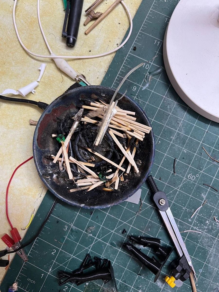
Another concern was ignition safety. I didn’t want to have a wired fuse system, since that would entail being up close to the rocket during ignition (no, I don’t trust myself to run away fast enough). To ensure I could ignite the rocket from a safe distance, I built an electronic ignition system powered by a battery pack. This used nichrome wire wrapped around a matchstick (which was then inserted into the nozzle - when the propellant ignited, the exhaust gases pushed the igniter out of the nozzle, automatically clearing it).
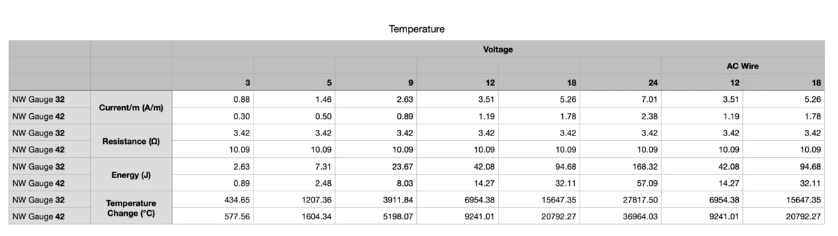
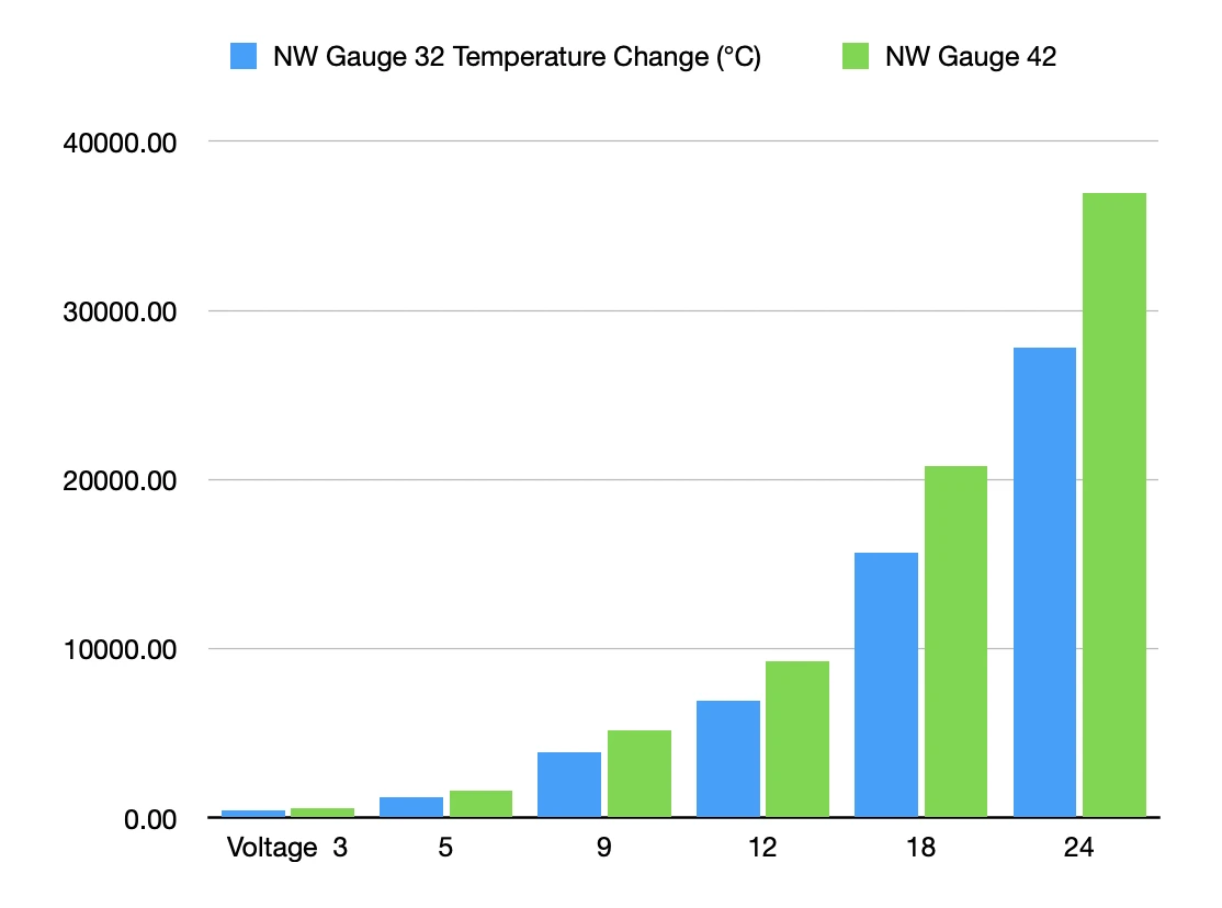
I used the equation: $$\Delta T=\frac{q}{mc}=\frac{I^2R}{mc}$$ Where $\Delta T$ is change in temperature, $q$ is energy, $I$ is current, $R$ is resistance, $m$ is mass and $c$ is specific heat capacity (since I was calculating the change in temperature per unit time, I used $q=I^2R$ instead of $q=I^2Rt$).
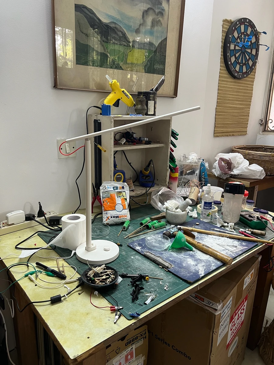
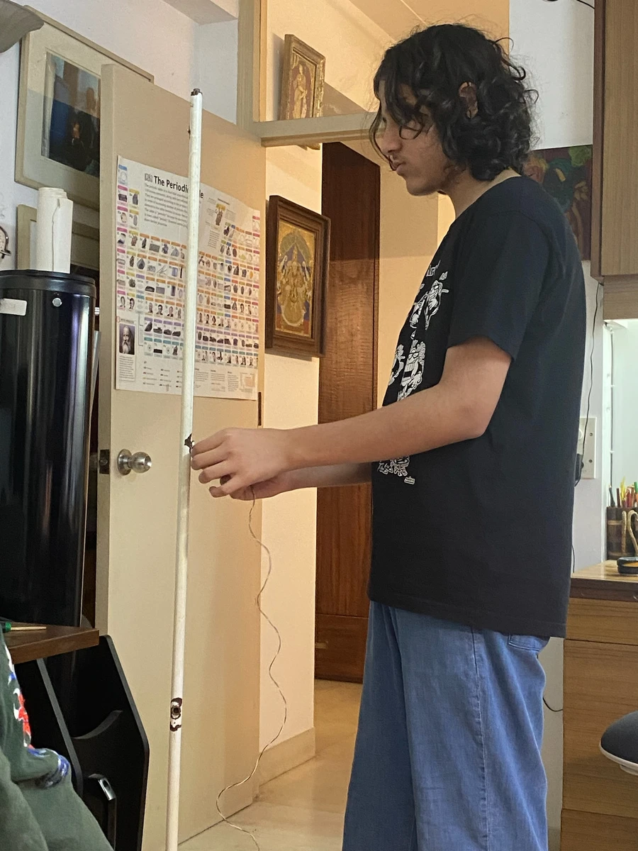
The EIS was installed in an iron lamp-rod, which was chosen to be the launch pad. The lamp rod extended till above my eyeline (for safety) and had a hole in the top where the rocket could be installed. The rod was also hollow, so the wire for the EIS was fed through this. Come launch, I simply had to plug the USB into the battery pack, and ignition.
Caramelin Series
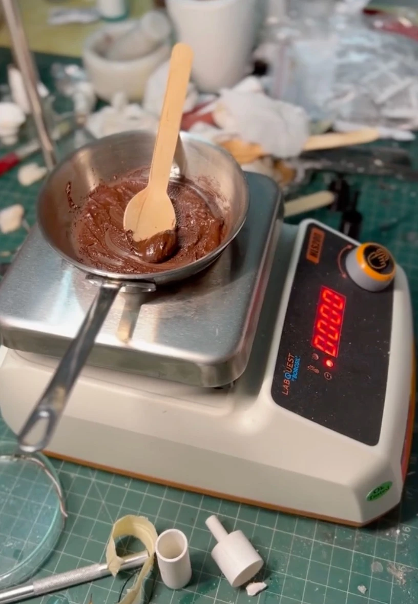
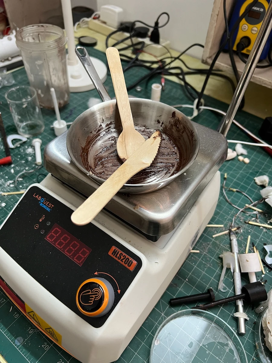
The Sucrose rockets rarely gave me anything resembling vertical flight - indeed, out of the nine rockets launched only one flight was semi-vertical. One significant problem was that in a powder based propellant, I could not ensure that the mixture was completely homogenous. To deal with this issue, I decided to switch to cast-propellant rockets. This entailed melting the sucrose (hence the name Caramelin), dissolving the potassium nitrate and then moulding the propellant. The problem with this was that sucrose has quite a high melting point, which makes it difficult (and scary, since we’re heating the propellant to a higher temperature) to mould, and it quickly starts to caramelise, which degrades the propellant quality. Though I was carefully heating the propellant on a hot plate at a controlled temperature, caramelisation was unavoidable, and the hot propellant which solidified quickly was impossible to properly pour into the 3D printed moulds.
Delta Series
The Delta series rockets (named after the symbol for energy in chemistry, Δ) featured four major improvements to the whole system that significantly smoothened all future launches.
- I finally switched to casting the propellant. Replacing the sucrose with sorbitol (with a much lower melting point) made the propellant grains much easier to cast. Sorbitol also remains pliable for quite some time after casting; neither does it caramelise. However, sorbitol lacks the glycosidic bond that sucrose contains, and therefore it releases less energy per gram of propellant as compared to sucrose. To deal with this, I “doped” the grains with a little bit (1% by mass) of iron oxide, which is a burn rate catalyst.
The chemical equation for the combustion of the propellant is:
$$C_6H_{14}O_6+3.345KNO_3\rightarrow 1.870CO_2+2.490CO+4.828H_2O+2.145H_2+1.672N_2+1.644K_2CO_3+0.057KOH$$
Casting the propellant 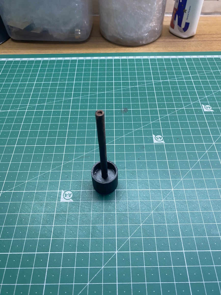
Part of the propellant mould - To stabilise the rocket during flight, I added fins to the body. Since I was custom printing the body, this was very easy to do.
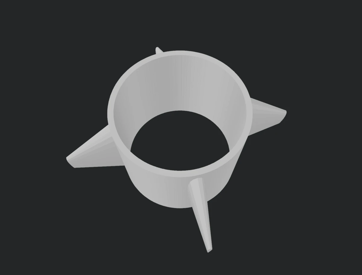
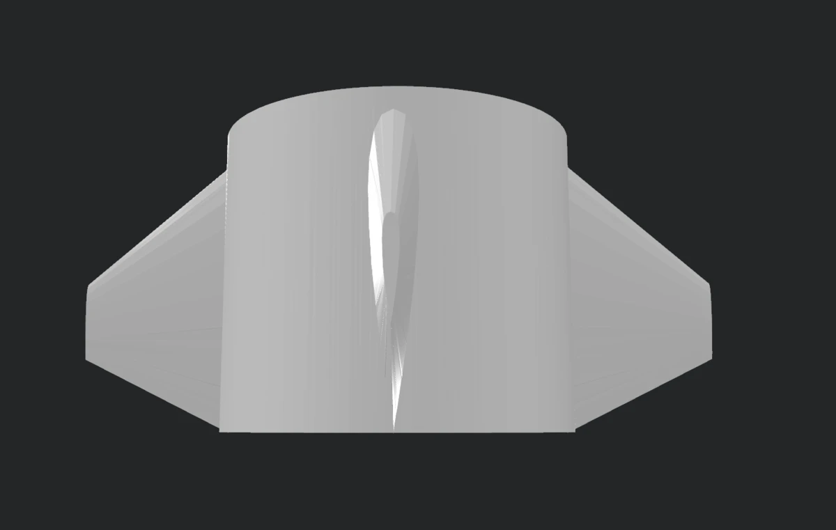
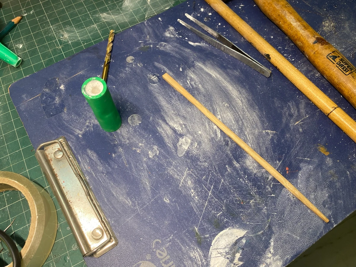
Fins 3D model. The system was designed to be modular - for any one of the standard rocket bodies to be given fins, this unit simply had to be slid around the outside at the bottom. The fit was sufficiently tight enough - The launching mechanism used for the Sucrose series was extremely crude: a light bamboo stick taped to one side of the body, and then placed inside the hole in the launch rod up top. This messed up the centre of gravity of the rocket, making it go topsy-turvy. To counteract this, I designed and 3D printed a dedicated launch pad which used a thin knitting needle as a guide rail. The fin module was modified to attach to the guide rail. This created a really neat launch system.
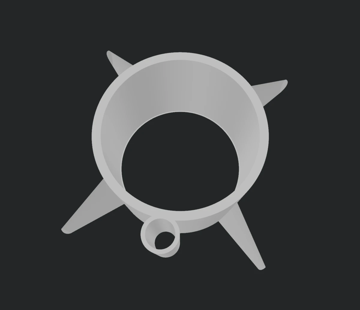
Modified fin module with a thin tube to attach to the guide rail 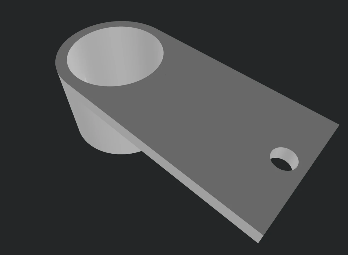
3D model of the launchpad. The big hole on the left is used to fit the launchpad on the launch rod, and the small hole on the right is where the knitting needle guide rail was installed 
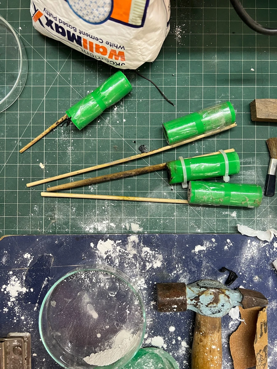
(Left) Launchpad attached to launch rod, (right) fin module attached to guide rail - The putty that I was using to cap off the propellant on both sides needed to be made wet to properly function as a seal. This meant that I risked contaminating the propellant with water - which would slow down the burn rate. In the early Sucrose models (S1-S2) I was using dry, compressed putty seals, but in two launches they gave way. In later Sucrose models (S3 onwards), I started wetting the putty very slightly, and this gave initially promising results (like with S3M3). Then, for two successive launches (S3M5 and S3M6) the rockets did simply not lift off, and the diagnosis is that this was because the thrust was very weak - the propellant had been contaminated with water. To prevent this, I 3D printed a small “spacer” that was placed between the propellant and the putty. This ensured the propellant remained mostly dry.
Additionally, I started dehydrating the finished rockets to really get a good burn.
Eventually, I demonstrated my rocket project on National Science Day (28th February, 2024) in school, launching a series of Delta series rockets.