In attempts to digitise my guitar rig - currently consisting of a Boss Katana 50 MkII and a XSonic Airstep Kat foot-switch, which are a pain to lug around since the amp is so heavy - I started building a MIDI foot controller using the Arduino Uno R4 Wifi, which can be used in combination with my DAW. This would make my setup much more portable (since it would now consist only of my laptop, the compact foot-switch and my audio interface), and much more versatile, since I would have access to so many more digital presets and effects as compared with the Katana.
April 26th, 2026
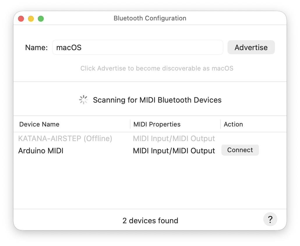
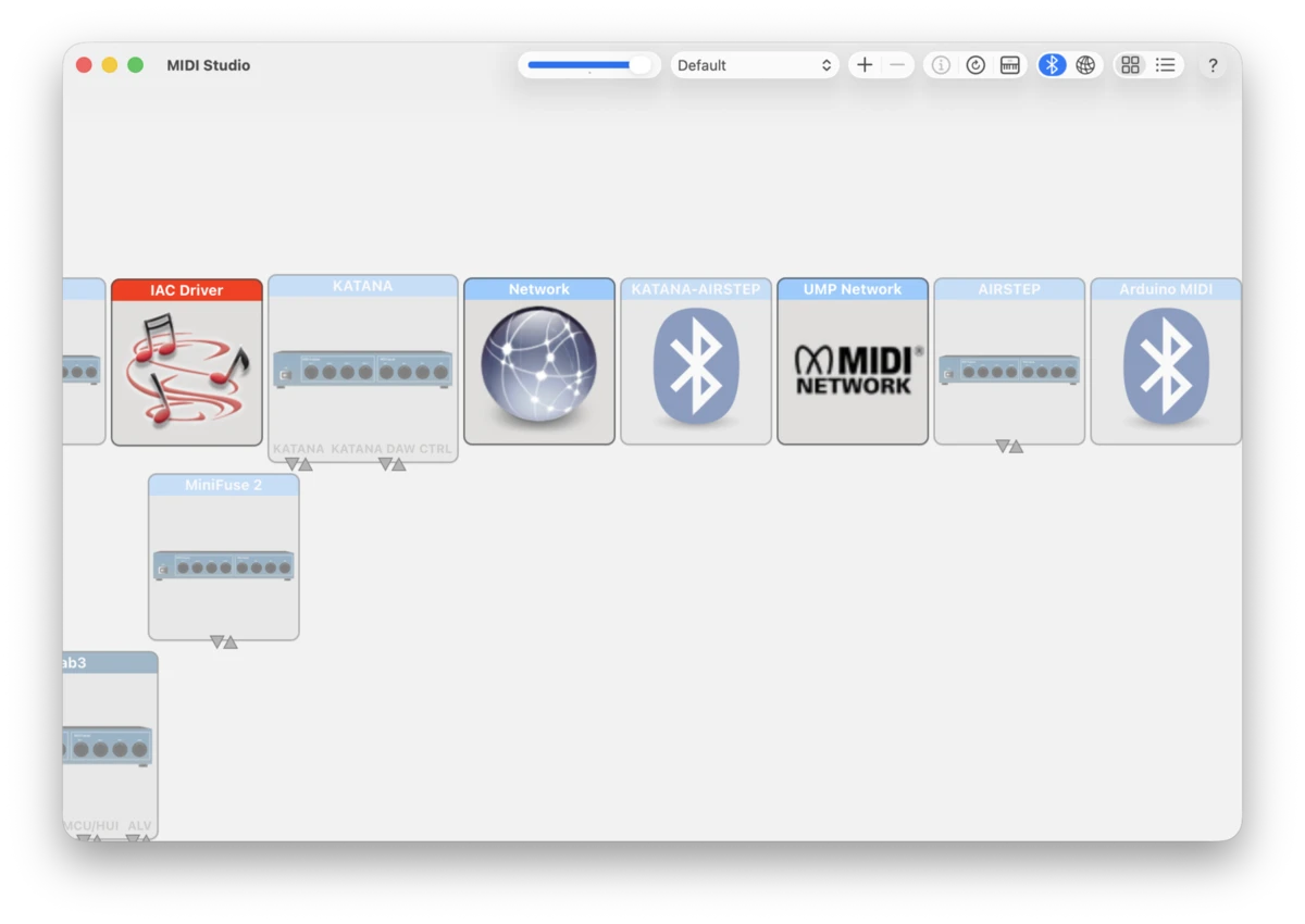
I started by getting my Mac to register the Arduino as a bluetooth MIDI device, and for my DAW to register incoming MIDI signals from the Arduino.
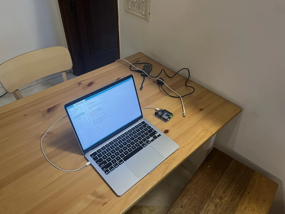
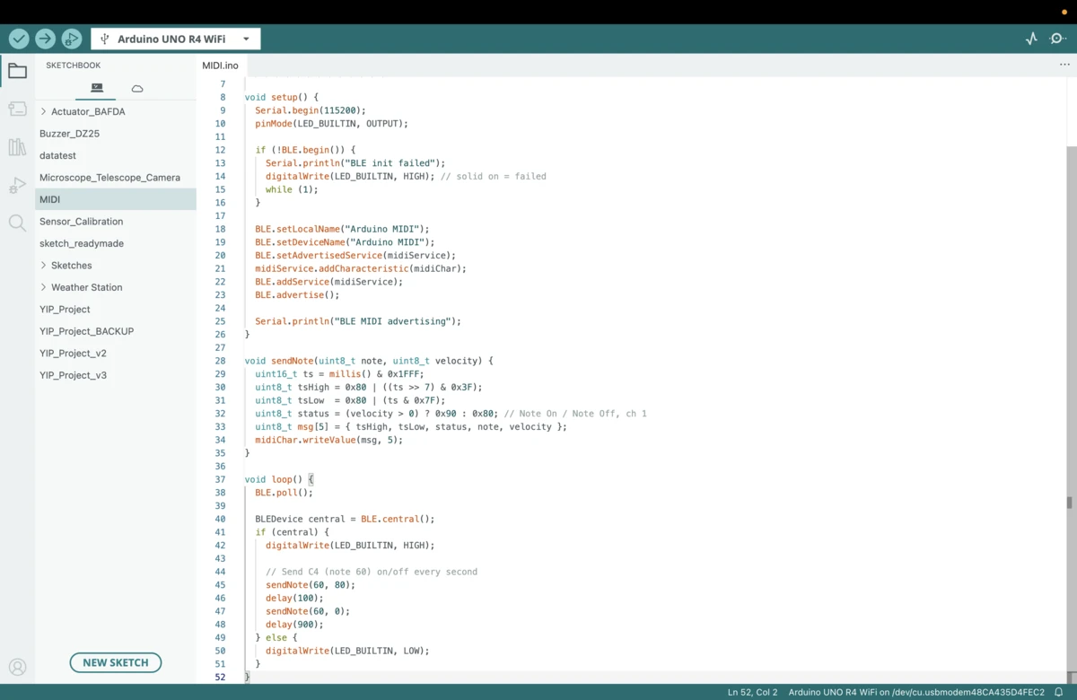
I was able to connect to the Arduino via Bluetooth through Audio MIDI Setup. After this, the Arduino started showing up in MIDI studio.
April 30th, 2026
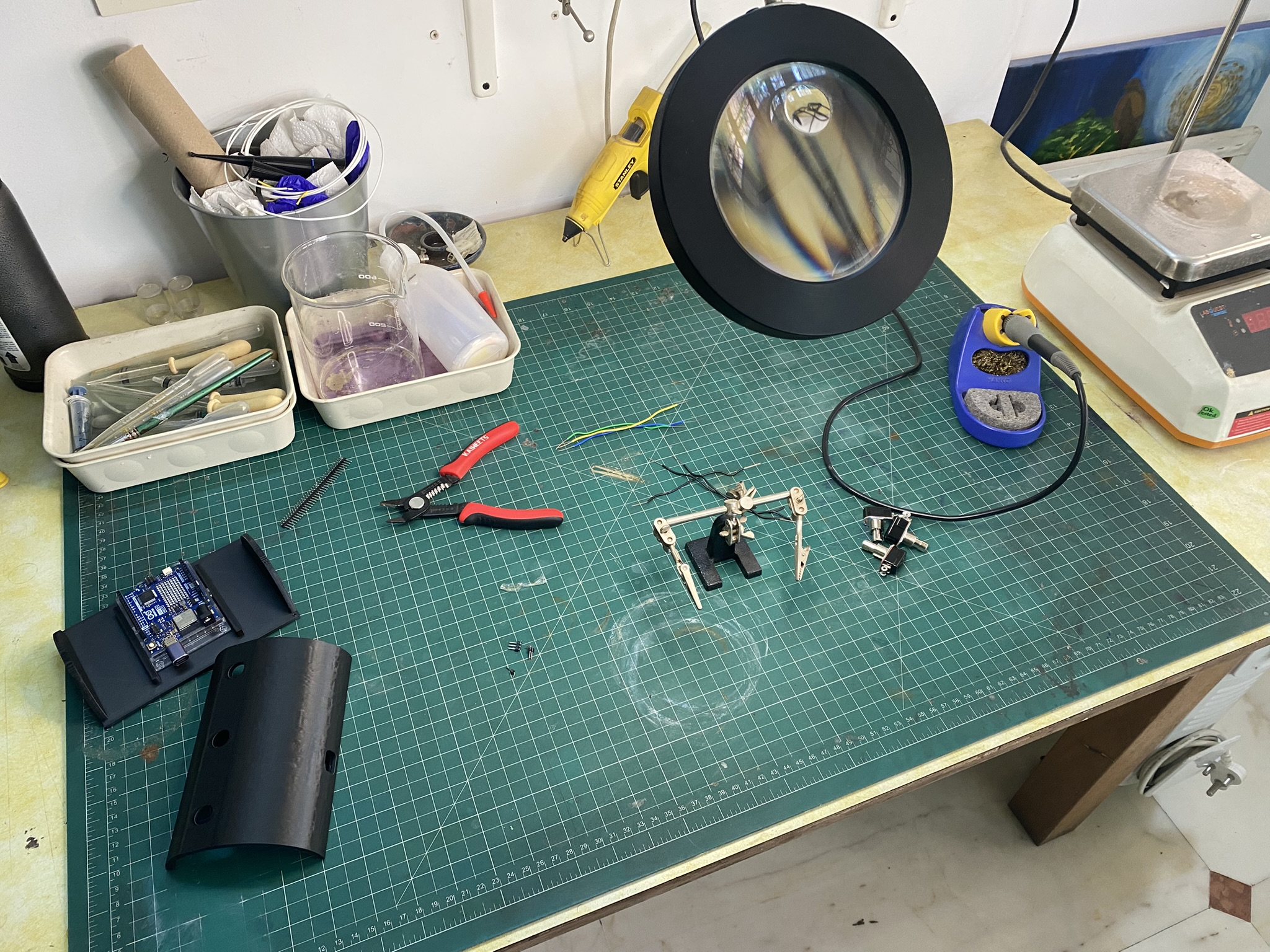
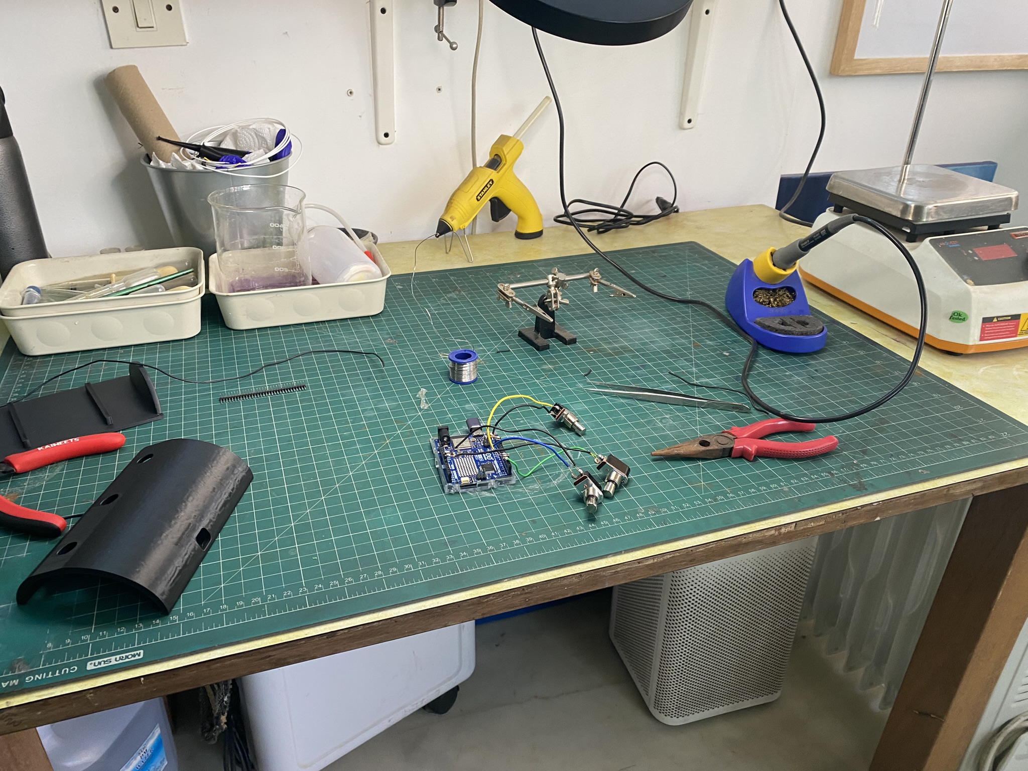
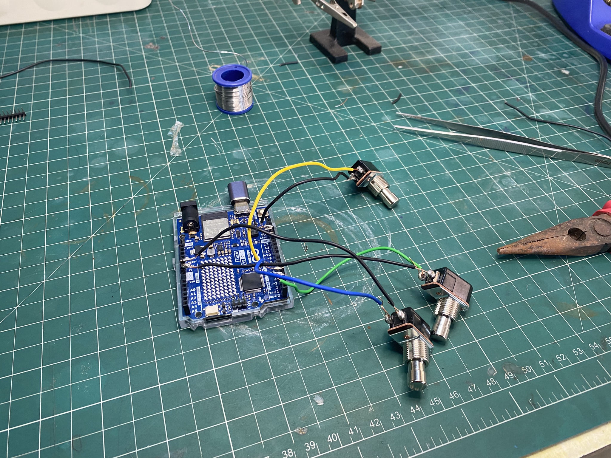
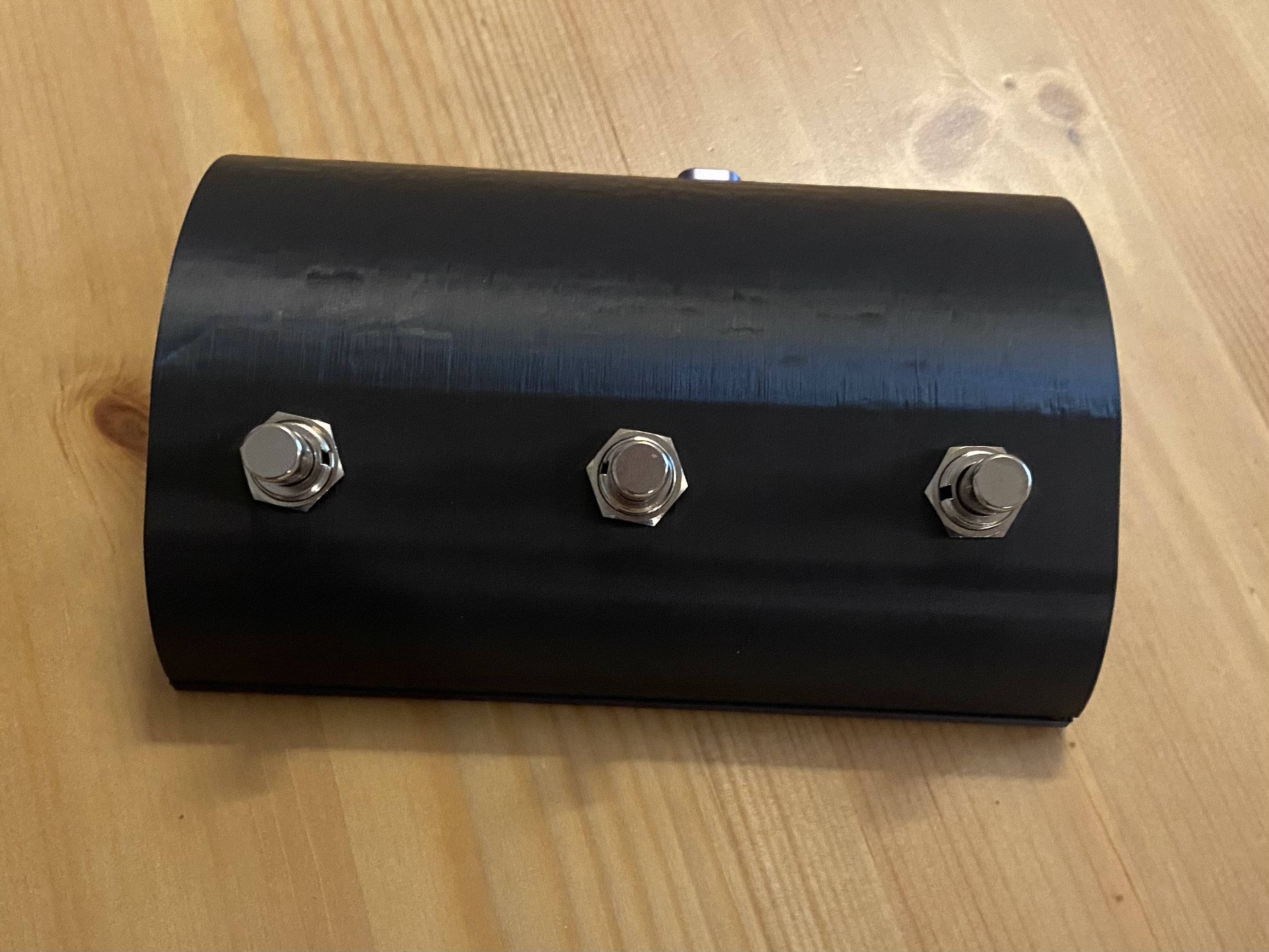
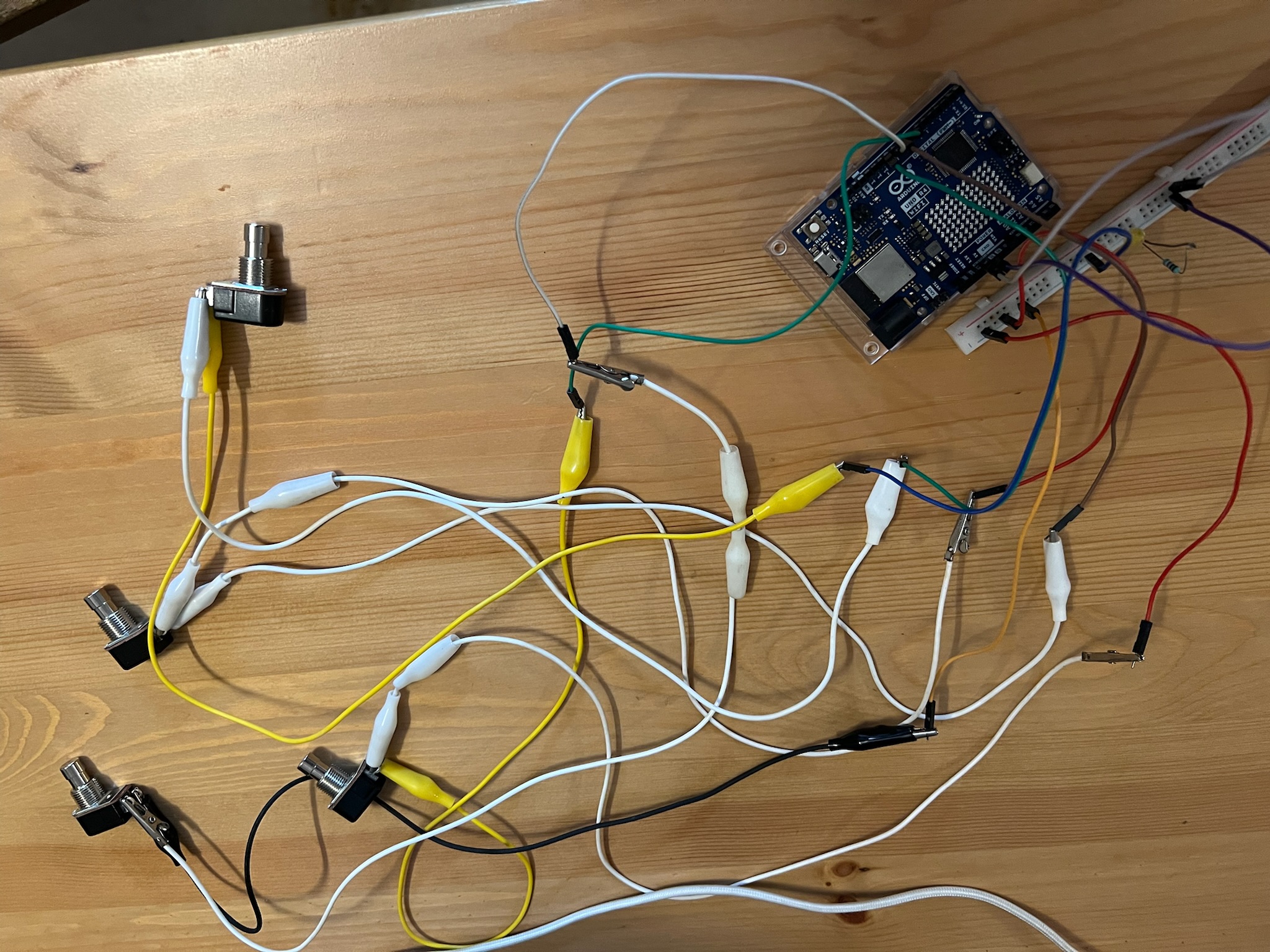
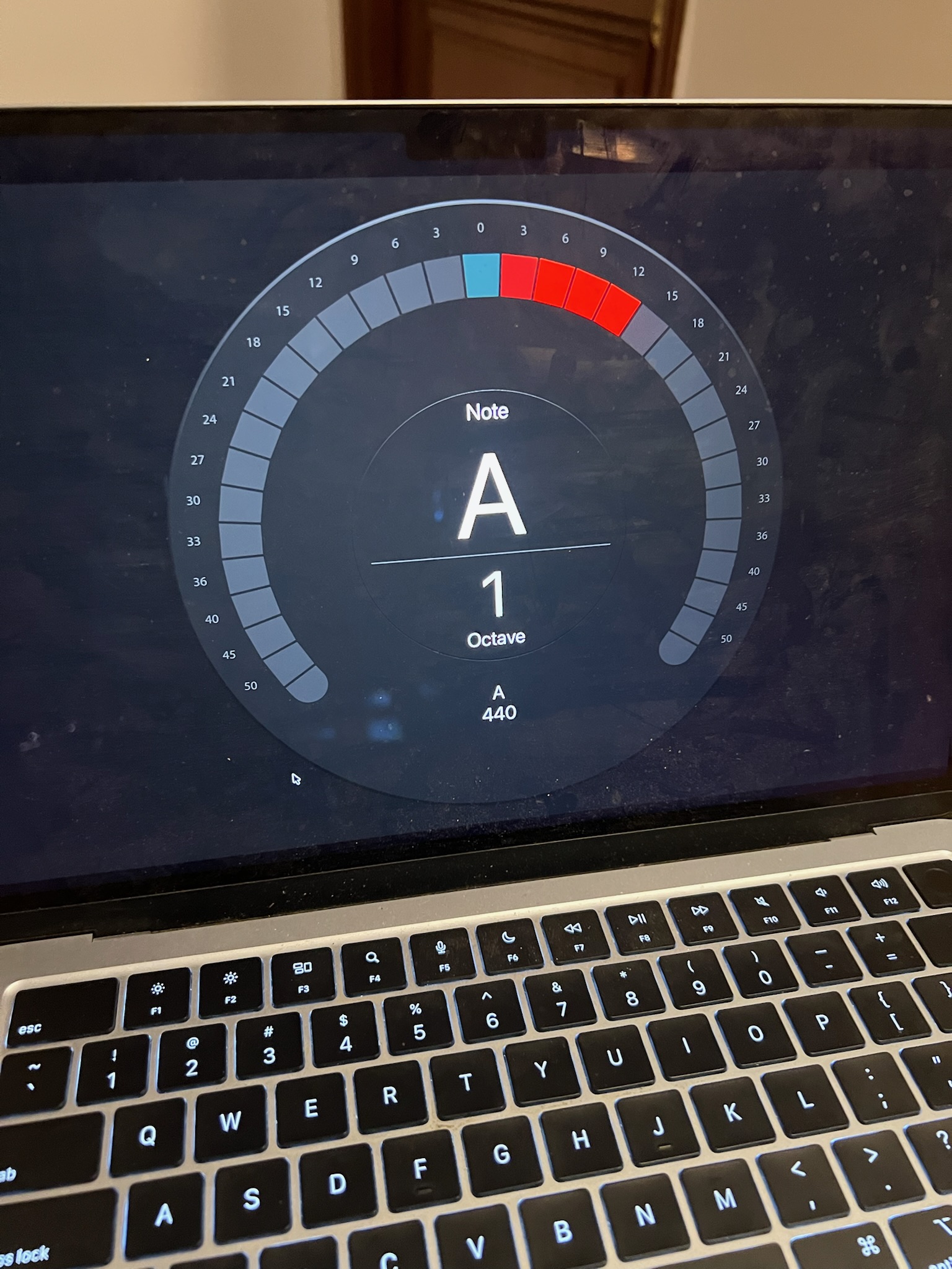
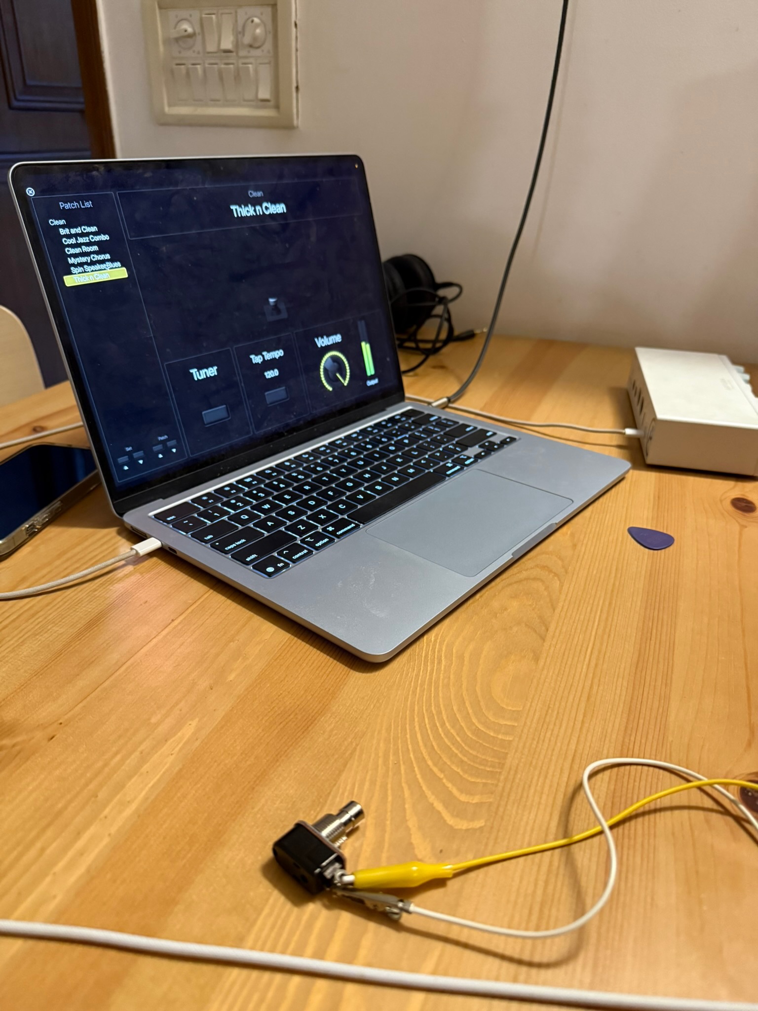
Today was spent finalising the circuit, and getting the system to work with Apple’s MainStage application. The final circuit consists of three switches: one to trigger the tuner, one to move to the next patch, and one to move to the previous patch. The Arduino sends MIDI CC signals (different ones depending on which switch you press), which can be mapped in MainStage to any assignment.
May 1st, 2026
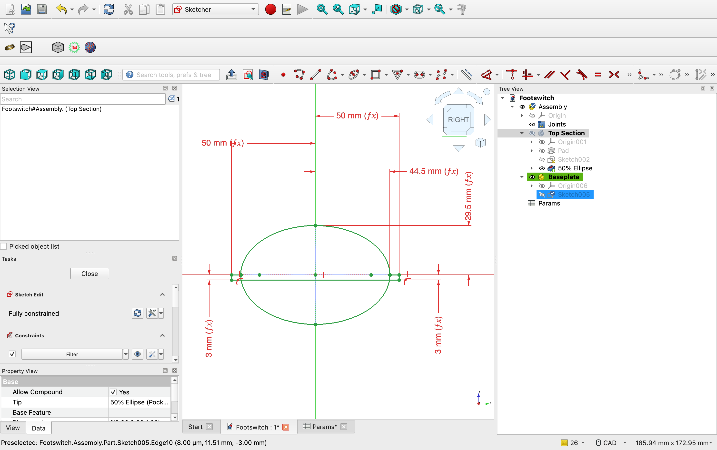
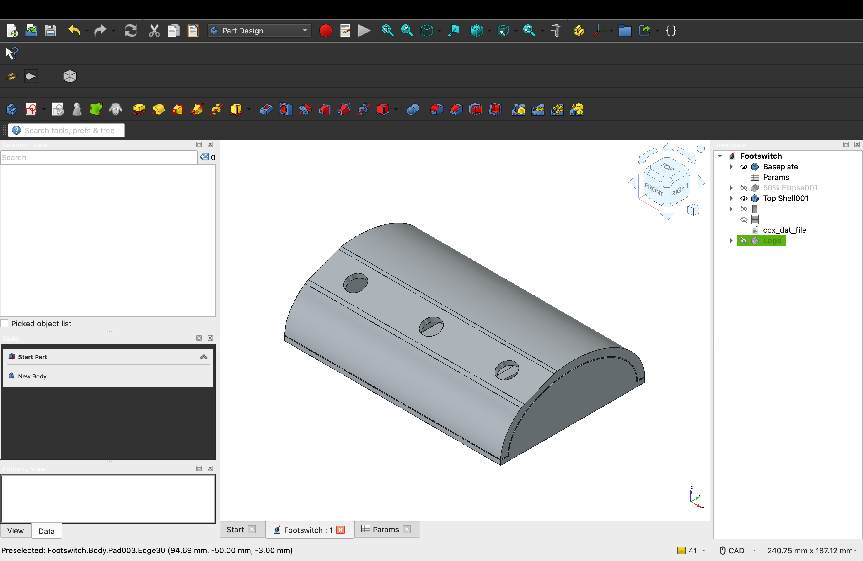
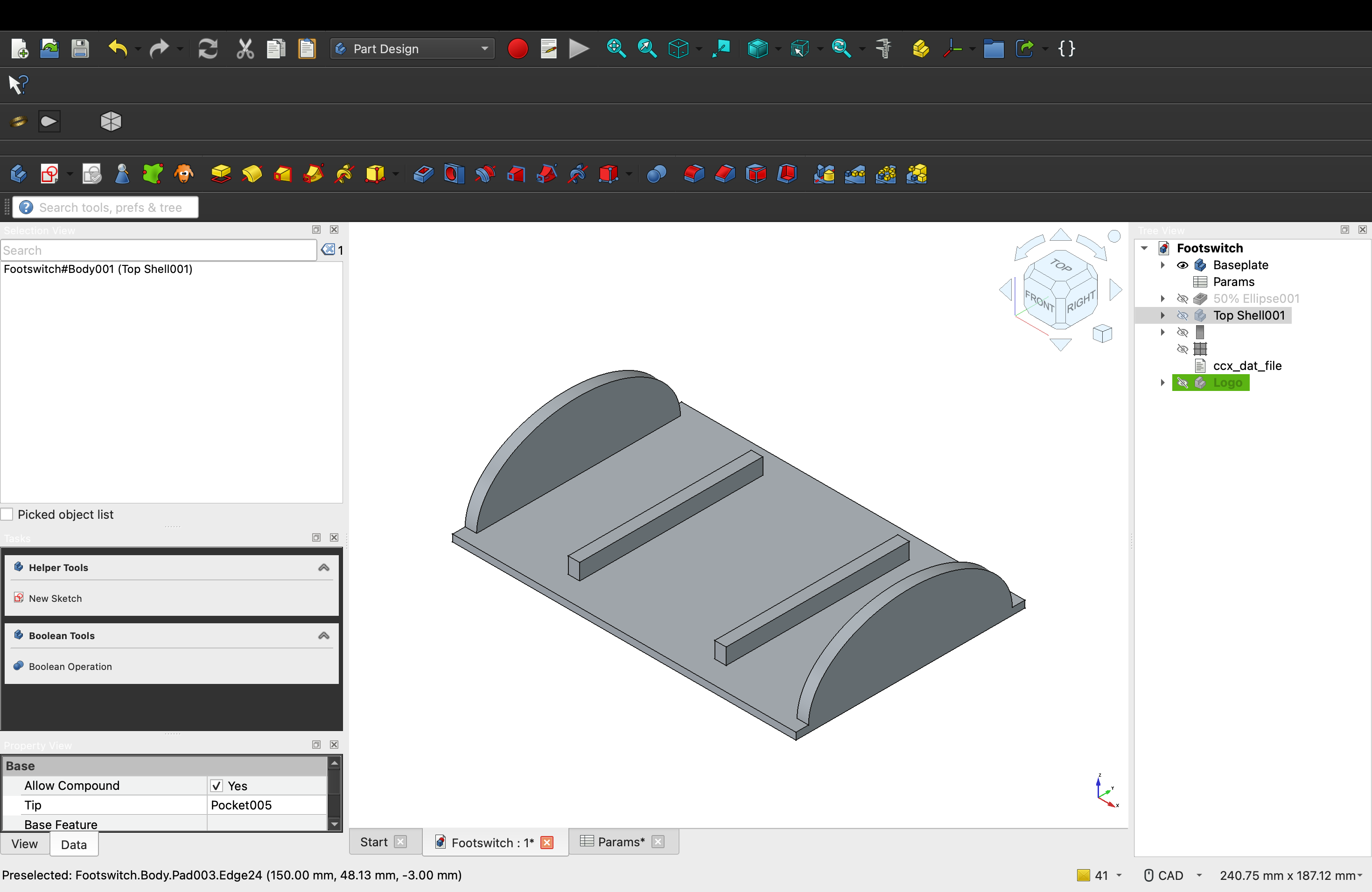
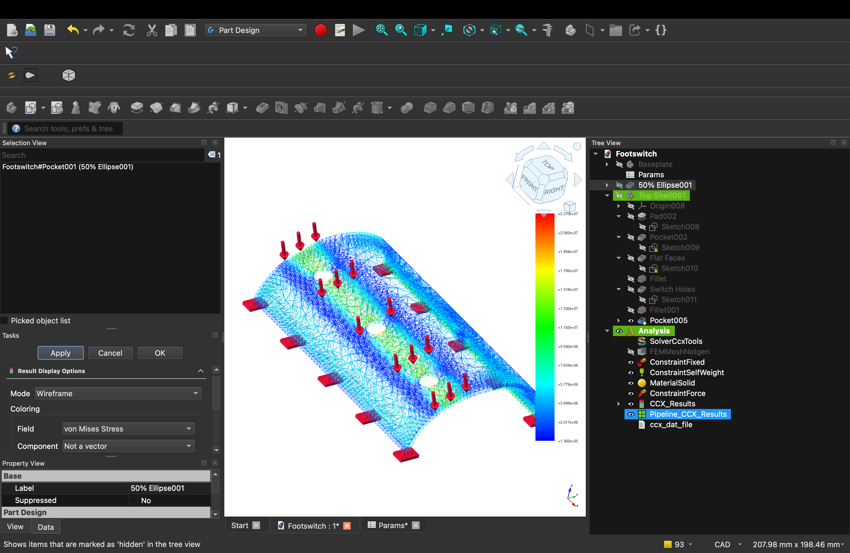
Today was spent designing the enclosure. I used FreeCAD to do the 3D design and Finite Element Analysis (FEA), opting to use a curved profile (an ellipse) rather than a rectangular one, enabling the model to better handle the stress it would be under.
May 2nd, 2026
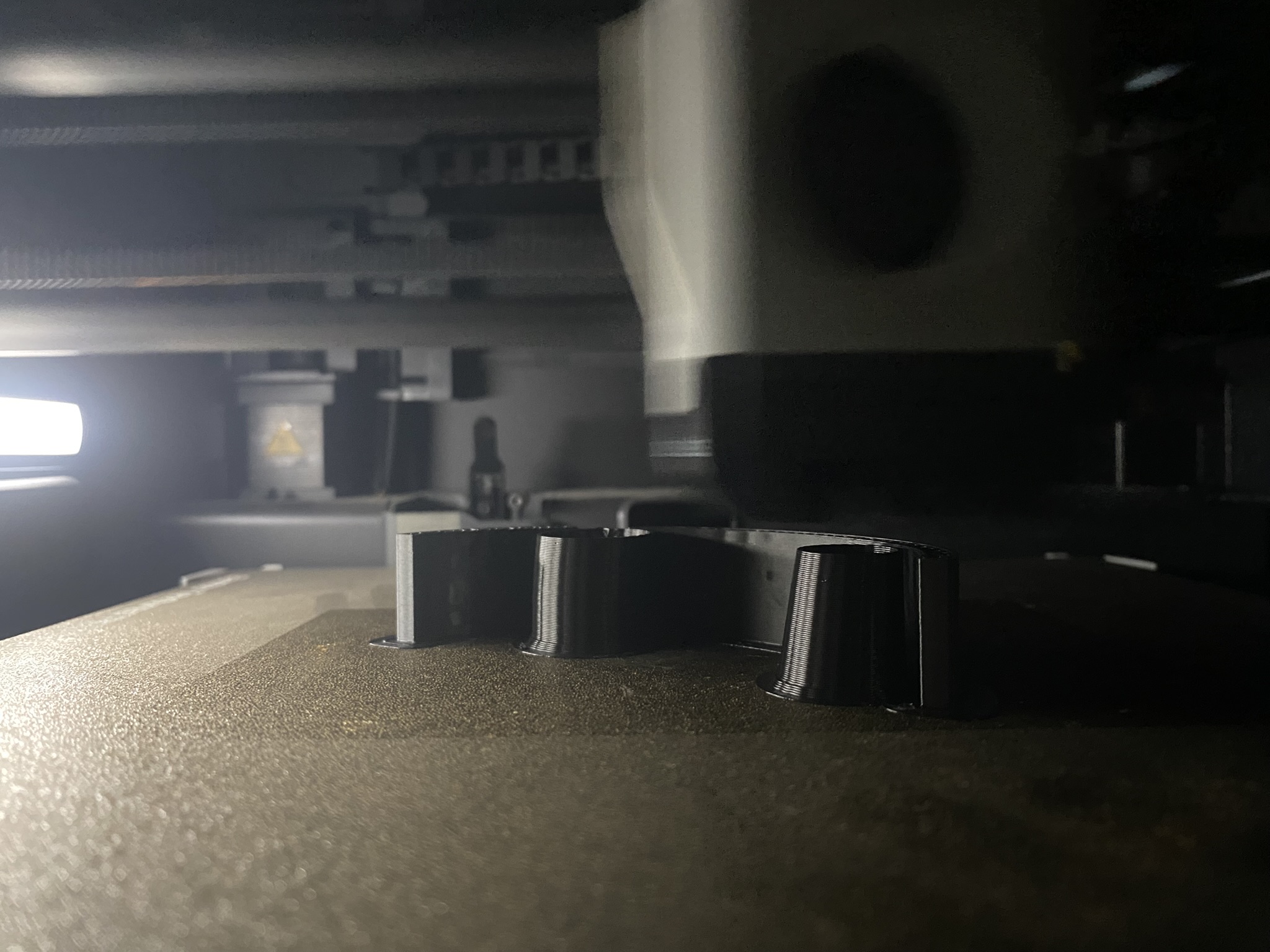
Today I completed Footswitch MK1. After printing the design, I soldered al the components together and assembled them into the shell.